
Product Manual


page 8
WARNING!
To reduce the risk of injury, do not operate the saw without the
guards in place.
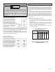
Installing the Blade Guard (Fig. 8)
Always install the blade guard before operating the saw. The guard is
shipped with the chatter guard pushed up inside the blade guard and
three torque knobs installed. Reach up into the blade guard and pull
down the chatter guard. Remove the knobs to install the guard. Leave the
rubber washers on the torque knobs to prevent the knobs from slipping.
1. Make sure the tool is unplugged.
2. To attach the guard, line up the torque knob holes on the blade guard
and the saw carriage (Fig. 8).
3. Install the three torque knobs.
4. Return carriage to the top of guide tubes and tighten carriage lock.
5. Reverse the procedure to remove the blade guard.
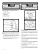
Installing the Cord Keeper (Fig. 9 & 10)
The cord keeper keeps the cord away from the saw blade and away
from your workpiece.
1. Pinch the ends of the cord keeper together while slowly sliding them
into the guide tubes (Fig. 9). Seat the ends securely.
2. Remove the rubber stopper from the ring in the cord keeper (Fig. 10).
3. Uncoil the cord and place the plug end through the ring.
4. Loosen the carriage lock and lower the saw carriage to the bottom
of the guide tubes. Tighten the carriage lock.
5. Pull the cord keeper so it is parallel to the floor. Pull on the cord to
remove slack in the cord.
6. Open the rubber stopper and pull it over the cord with the small end
of the taper toward the bottom.
You are now ready to use your panel saw. Refer to the "Operation"
section for instruction on proper use.
Panel Saw Alignment
The panel saw is aligned during manufacturing to a tolerance of ±1/32".
Field alignment is required only if the unit is mishandled or abused, or if
motor or wheel replacement is required.
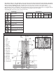
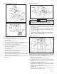
Construct a field alignment tool (Fig. 11):
For maximum accuracy, manufacture a test square (Fig. 11) to check the
full movement of the saw. Construct the square using one 6' metal ruler
and two 4' metal rulers. Using the 3'-4'-5' measurements assures
squareness. Drill holes and attach the rulers with pop rivets or small nuts
and bolts. Use the 6' ruler to check squareness of the rollers and the 4'
ruler to check squareness of the guide tubes. The tool also acts as a
giant square for layouts.
The alignment process consists of 4 steps which must be performed in
the following order.
Step 1 - Adjusting the Rollers
1. To check roller alignment, remove extensions (if present).
2. Retract the stand and lay the tool flat so the roller nuts are easily
accessible. With proper care, you may place the tool on a table with
guide tubes up.
3. The outermost rollers are stationary, so adjust all other wheels to
the two outermost rollers. Lay the straight edge of the field align-
ment tool across the rollers to verify alignment; all rollers should
contact the edge.
4. If a roller is "high" or "low" to the straight edge, clamp a straight edge
at least 5' long to the top of the rollers so it lies flat on the frame and
against the outermost rollers, positioning the clamps above the out-
ermost roller.
5. With the straight edge clamped securely in place, rotate each roller
to be sure that it neither jams nor has excessive clearance to the
straight edge. If a roller runs "tight" or "loose" to the straight edge,
loosen the roller nut. Roller nuts are torqued and require at least an
18" braker bar to loosen them.
6. The rollers are mounted on an eccentric hub. Turning a roller when
the roller nut is loose will cause the roller to change its position. You
may have to lift the front roller carriage bar to rotate the eccentric
hub. Turn the roller until it contacts the straight edge, being careful
not to bend or bow the straight edge when repositioning the wheel.
Tighten the roller nut securely, making sure the roller does not change
position. Repeat this process as needed for the remaining rollers.
7. Reposition the tool upright.
Fig. 11
5'
4'
3'
6'
Line up on
36" mark
4' frame support
7. Press the rubber stopper into the ring on the cord keeper with the
small end facing down. If the small end of the taper is on the top, the
stopper will not keep the cord in place.
8. Loosen the carriage lock and allow the saw carriage to return to the
top of the guide tubes. Tighten the carriage lock.
NOTE: If you discover there is too much or not enough slack in the
cord, readjust as necessary.
Fig. 8
Chatter
guard
Blade guard
Torque
knobs
Torque
knob
Torque
knob hole
Torque
knob holes
Fig. 9
Cord
keeper
end
Guide
tube
Rubber
stopper
Fig. 10
Saw
carriage
Taut cord
Cord
keeper