
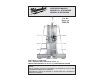
Use and Care Manual


6
7
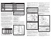
Grounded tools require a three wire extension
cord. Double insulated tools can use either a two
or three wire extension cord. As the distance from
the supply outlet increases, you must use a heavier
gauge extension cord. Using extension cords with
inadequately sized wire causes a serious drop in
voltage, resulting in loss of power and possible tool
damage. Refer to the table shown to determine the
required minimum wire size.
The smaller the gauge number of the wire, the
greater the capacity of the cord. For example, a 14
gauge cord can carry a higher current than a 16
gauge cord. When using more than one extension
cord to make up the total length, be sure each cord
contains at least the minimum wire size required. If
you are using one extension cord for more than one
tool, add the nameplate amperes and use the sum
to determine the required minimum wire size.
Guidelines for Using Extension Cords
• If you are using an extension cord outdoors, be sure
it is marked with the suffi x “W-A” (“W” in Canada)
to indicate that it is acceptable for outdoor use.
• Be sure your extension cord is properly wired
and in good electrical condition. Always replace a
damaged extension cord or have it repaired by a
qualifi ed person before using it.
• Protect your extension cords from sharp objects,
excessive heat and damp or wet areas.
READ AND SAVE ALL
INSTRUCTIONS FOR FUTURE USE.
Recommended Minimum Wire Gauge
for Extension Cords*
Extension Cord Length
* Based on limiting the line voltage drop to
fi ve volts at 150% of the rated amperes.
Nameplate
Amperes
0 - 2.0
2.1 - 3.4
3.5 - 5.0
5.1 - 7.0
7.1 - 12.0
12.1 - 16.0
16.1 - 20.0
25'
18
18
18
18
16
14
12
75'
18
18
16
14
12
10
100'
18
16
14
12
10
150'
16
14
12
12
50'
18
18
18
16
14
12
10
EXTENSION CORDS
ASSEMBLY
Assembly Order
To avoid injury or damage to the tool, follow the
order of sections in "Tool Assembly". Set up the
tool in the following order of sections:
1. Setting up the Stand
2. Installing the Counterbalance
3. Mounting the Saw Motor
4. Installing Blades
5. Adjusting the Rulers
6. Installing the Blade Guard
7. Installing the Cord Keeper
Setting up the Stand
Use at least two people to remove packaging and
set up the stand. One person should hold the stand
in an upright position while the other removes the
packaging and sets the folding stand to make the
tool free-standing.
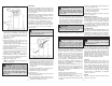
Installing the Counterbalance
Fig. 1
Fig. 2
Fig. 3
Counterbalance
Counterbalance
cable
Nut
Washer
Carriage
bolt
Cable
clip
Counterbalance
cable
Carriage
bolt
Cable clip tabs
Nut
WARNING To reduce the risk of injury,
always unplug tool before attaching or remov-
ing accessories or making adjustments. Use
only specifi cally recommended accessories.
Others may be hazardous.
position with one hand while holding the stand
base with your other hand so it does not unfold
onto your feet.
2. Unfold the stand slowly until the hole in the
sliding center bar is aligned with the hole in the
center bar.
3. Insert the locking pin through the holes and lock
it securely.
WARNING To reduce the risk of injury
or damage to components, do not attempt to
disassemble or repair the counterbalance.
Do not pull on the counterbalance cable.
The cable is under strong spring force. Unit
must be properly assembled before removing
cable clip.
1. Remove the (2) 1/4 - 20 nuts, (2) washers
and (2) 1/4"-20 x 5/8" carriage bolts from the
counterbalance. Leave the nut and bolt on the
counterbalance cable in place.
2. Remove the end of the cable from the inside of
the counterbalance. The counterbalance must
be installed off-center to the right (while facing
the saw from the front): holes are cut into the top
of the tool frame.
3. Secure the counterbalance to the tool using (2)
carriage bolts, (2) washers, and (2) nuts.
NOTE: The carriage bolts are installed from the
bottom up. Tighten nuts securely.
Symbology
Double Insulated Volts Alternating Current
Underwriters Laboratories, Inc. Amperes
Underwriters Laboratories, Inc.,
Recognized Component
Do not place hands on or under
saw carriage or in the path of the
blade.
No Load Revolutions per Minute
(RPM)
Do not expose to rain or use in
damp locations.
Sliding
center bar
Folded locking
pin position
Locking pin
Center bar
Unfolded locking
pin position
Stand base
1. While having another person hold the stand in
the upright position, stand behind the tool. Re-
move the locking pin from the folded locking pin
4. Hold the saw carriage securely while loosening
the carriage lock.
5. Raise the saw carriage until the oval hole in
the saw carriage aligns with the eye hole in the
counterbalance cable, making sure the cable is
behind the saw carriage.
6. Tighten the carriage lock.
7. Remove the nut from the carriage bolt and insert
the bolt through the hole in the saw carriage and
the eye hole in the counterbalance cable. Thread
the nut onto the bolt and tighten securely.
8. Bend the cable clip tabs down by hand.
9. Loosen the carriage lock and lower the saw car-
riage until the cable clip is fully exposed.
10.Tighten the carriage lock.
11.Remove the cable clip from the counterbalance
cable and save it for future use (i.e., If you re-
move the counterbalance in the future, you will
need the cable clip to support the tension in the
counterbalance.)
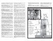
Mounting the Saw Motor
Fig. 4
Bracket
Studs
9/16" Nuts
and washers
Spacer
7/16" Nut
and washer
Bolt
Bracket
Saw
carriage
Fig. 5
Leveling
screw
The motor is shipped with (3) washers, (3) nuts,
(1) spacer, and (1) bolt. Remove these items to
mount the saw.
1. Loosen the carriage lock and lower the saw car-
riage to a comfortable work height.
2. Tighten the carriage lock securely.
3. Mount the motor to the saw carriage by inserting
the studs on the saw motor through the holes in
the saw carriage (Fig. 4).