
Use and Care Manual


4
5
3. Storage for an additional pad is available on the
magazine of the tool.
4. To replace the pad, fi t it into place over the points of
the claw.
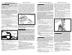
Exhaust
The exhaust cap can be adjusted to direct the exhaust
as desired. Turn the exhaust cap to the desired lock-
ing position.
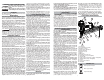
Removing and Installing the Rafter Hook
Rafter hook
Front of tool
End cap
Screw (2)
3/8" NPT
quick
connector
To remove the hook:
1. Rotate the hook until it snaps into one of the preset
positions.
2. Remove the two mounting screws using the wrench
provided.
3. Pull the hook off the rear of the tool.
To install the hook:
1. Align the spring-loaded post on the hook with a slot
on the rear of the tool.
2. Slide the hook onto the tool, making sure the hook
points toward the front of the tool. Push the hook up
against the end cap.
3. Install the two mounting screws using the wrench
provided. Tighten securely.
4. Verify that the hook is installed correctly by fi rmly
pulling the hook toward the air inlet. It must not move.
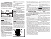
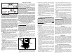
Lubricating the Tool
Lubricate the tool with air tool lubricant before connect-
ing the air supply. Under low use, lubricate once a day.
Under heavy use, lubricate twice a day. Use only a few
drops of oil at a time. Using too much oil will cause it to
collect in the tool and be noticeable in the exhaust. Do
not use detergent oil, WD-40, transmission fl uid, motor
oil, or other lubricants not specifi cally designated as air
tool lubricant. These lubricants will cause accelerated
wear to the seals, o-rings and bumpers in the tool, result-
ing in poor tool performance and frequent maintenance.
2-3 drops of air
tool lubricant
3/8" NPT quick
connector
Connecting the Air Supply
DANGER
Do not use oxygen, combustible
gases or bottled gases as a power
source for this tool. The tool will explode and cause
death or serious injury.
WARNING
Always use a coupling that dis-
charges all the compressed air in the
tool at the time the fi tting or hose coupling is dis-
connected. Using a coupling that does not dis-
charge the compressed air could cause unintended
operation and serious injury.
Use only clean, dry compressed air with a maximum
pressure of 200 psi. Before connecting the tool to the
air supply, check the air compressor regulator gauge to
be sure it is functioning properly, with a range between
70-120 psi. Air pressure higher than 120 psi could cause
injury and property damage. The correct pressure is the
lowest pressure that will do the job.
To connect the air supply:
1. Remove the plastic plug from the quick connector.
2. Lubricate the quick connector with 2-3 drops air tool
lubricant.
3. Snap the air hose onto the quick connector.
4. Check for air leakage.
NOTE: Use only a 3/8" NPT quick connector. To improve
the seal between the connector and the tool, and to help
protect against oxidation, apply a PTFE tape or paste
to the connector threads before insertion.
Installing Fastener Strips
WARNING
Always point the tool away from
yourself and others when installing
fasteners. Failure to do so could result in injury.
Always make sure the tool's magazine is EMPTY
before connecting to the air supply. The tool may
actuate when the tool is fi rst connected to the air
supply. Always connect the tool to the air supply
before loading nails to prevent injury from unin-
tended actuation.
Never install fasteners with the workpiece contact
or trigger activated. Failure to do so could result
in injury.
Use only recommended fasteners of the correct
size, length, collation angle and head type, as
indicated on the tool's nameplate. Refer to the
"Accessories" section for information on recom-
mended fasteners. Other fasteners could result in
tool malfunction, leading to injury.
1. Verify that the magazine is empty and then connect
the air supply to the tool.
2. Lay the tool on its side and point the nose of the tool
away from yourself and others.
3. Feed fastener strips into the magazine and over the
nail stop tab. Be sure the point of the fasteners is
pointed downward.
NOTE: Use only recommended fasteners of the
correct size, length, collation angle and head type
as indicated on the tool's nameplate.
4. Slide the pusher to the rear of the magazine and over
the nail stop tab.
5. Gently allow the pusher to slide forward, pushing the
fasteners toward the driving mechanism. The pusher
will stop when it rests against the end of the fastener
strip.
NOTE: The fasteners must be aligned with the nose
of the tool for the fasteners to be installed correctly.
SPECIFICATIONS
Cat. No. ........................................................7200-20
Operating Pressure .................................min. 70 PSI
..............................................................max. 120 PSI
Fastener Length ............................................. min. 2"
..................................................................... max.3.5"
Collation Angle......................................................22°
Fastener Size (Diameter) .........................min. 0.113"
................................................................ max. 0.148"
Air Consumption .................. 0.16 ft
3
/cycle at 100 PSI
Air Inlet ........................................................3/8" NPT
Magazine Capacity ...................................64-72 nails
TERMINOLOGY
Actuate
To cause movement of the tool component(s) intended
to drive a fastener.
Actuation System
The use of a trigger, workpiece contact and/or other
operating control, separately or in some combination
or sequence, to actuate the tool.
• Single sequential actuation
An actuation system that requires the workpiece con-
tact and then the trigger to be activated in a specifi c
sequence to drive a fastener. Additional actuation can
occur when the trigger is released and reactivated.
• Contact actuation
An actuation system that requires the workpiece con-
tact and the trigger to be activated in any sequence
to drive a fastener. Additional actuation can occur
when either the workpiece contact or the trigger is
released and reactivated.
• Selective actuation
An actuation system that allows selection of actua-
tion systems: single sequential actuation or contact
actuation.
Fastener
A staple, pin, brad, nail, or other fastening device which
is designed and manufactured for use in the tools.
Jam
An obstruction in the feed or drive areas of the tool.
Workpiece Contact
An operating control element on the tool intended to be
activated by the workpiece to be fastened.
ASSEMBLY
WARNING
Disconnect the air supply from the
tool and remove fastener strips be-
fore changing or removing accessories. Only use
accessories specifi cally recommended for this tool
by the manufacturer. Others may be hazardous.
The operator and other people in the work area
must wear eye protection in accordance with ANSI
Z87.1. Eye protection does not fi t all operators in
the same way. Make sure the eye protection chosen
has side shields or provides protection from fl ying
debris both from the front and sides.
No-Mar Pad
The No-Mar Pad on the nose of the tool protects the
workpiece when the workpiece contact is compressed
during actuation. The pad can be removed and re-
placed.
1. Before removing or replacing no-mar pads, discon-
nect the air supply from the tool and remove fastener
strips.
2. To remove the pad, pull the pad open and away from
the toe-nailing claw.
Removing Fastener Strips
WARNING
To avoid serious injury, disconnect
the tool from the air supply before
removing fastener strips or clearing a jammed
fastener.
Keep fi ngers clear of fastener track of magazine.
Pusher could pinch fi ngers, causing injury.
1. Lay the tool on its side and point the nose of the tool
away from yourself and others.
2. Disconnect the air supply from the tool.
3. To remove fasteners, press the pusher release button
on the pusher and gently slide the pusher forward
toward the driving mechanism.
4. Slide the nails back until they stop.
5. Press down on the fastener stop tab near the end of
the magazine and slide the fasteners over the tab.
6. Remove fastener strip from the tool.
7. Reload according to "Installing Fastener Strips".
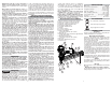
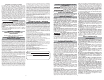
Clearing a Jammed Fastener
Most jams are caused by a fastener or part of a fastener
wedging between the driver blade and the nail guide.
Fastener strips with an incorrect collation angle or the
wrong fastener type (such as clipped head fasteners)
may cause continuous jamming. To clear the jam:
1. Lay the tool on its side and point the nose of the tool
away from yourself and others.
2. Disconnect the air supply from the tool and remove
fastener strip.
3. Insert a screwdriver into the end of the nail guide.
The tip of the screwdriver should contact the tip of
the driver blade.
4. Tap the screwdriver gently with a hammer. The
screwdriver will push the driver blade back, freeing
the jam.
5. Remove the fastener and other debris (use needle-
nose pliers if necessary).
6. Follow the steps under "Required Daily Testing"
before restarting the work.
Tap screwdriver
to free fastener