
Use and Care Manual


6
7
OPERATION
WARNING
The operator and other people in the
work area must wear eye protection
in accordance with ANSI Z87.1. Eye protection does
not fi t all operators in the same way. Make sure the
eye protection chosen has side shields or provides
protection from fl ying debris both from the front
and sides. The employer is responsible for enforc-
ing the use of eye protection by the operator and
other people in the work area. When required, wear
head protection in accordance with ANSI Z89.1.
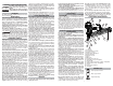
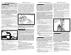
Selecting Actuation Mode
The selectable trigger can be set to either Single Se-
quential Actuation mode or Contact Actuation mode.
Single
Sequential
Actuation
Contact
Actuation
1.Push in and hold the Actuation Selector.
2. Rotate the Selector to Single Sequential Actuation
(T) or Contact Actuation (TTT).
3. Release the Actuation Selector.
NOTE: Be sure the selector is snapped into position.
Understand the actuation process before use.
WARNING
To reduce the risk of injury to your-
self and others, test the tool before
beginning work each day according to the "Re-
quired Daily Testing" section.
Do not use the tool unless you thoroughly under-
stand the actuation operation selected.
Disconnect the air supply from the tool and remove
fastener strips before leaving the work area, mov-
ing the tool to another location, or handing the tool
to another person. Failure to do so could result in
serious injury.
Do not carry an air hose or a tool connected to an
air hose when climbing ladders, rigging or scaffold-
ing. Do not attach an air hose or tool connected to
an air hose to your body when working at elevated
heights. Attach the hose to the structure to reduce
the risk of loss of balance and injury if the hose
shifts.
Do not use this tool for fastening electrical
cables. It is not designed for electric cable
installation and may damage the insulation of
electric cables thereby causing electric shock
or fi re hazards.
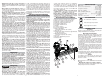
Single Sequential Actuation Operation
1. Grip the handle fi rmly.
2. Position the nose of the tool on the work surface.
3. Push the tool against the work surface, compressing
the workpiece contact.
4. Pull the trigger to drive the fastener. The tool will recoil
away from the workpiece as the fastener is driven.
5. Remove your fi nger from the trigger and remove the
tool from the workpiece.
NOTE: If the tool is not removed from the workpiece,
another fastener may be driven if the trigger is pulled
again.
Contact Actuation Operation
1. Grip the handle fi rmly.
2. Pull and hold the trigger.
3. Push the tool against the work surface, compressing
the workpiece contact to drive the fastener. The tool
will recoil away from the workpiece as the fastener
is driven.
NOTE: Contact Actuation will also work by fi rst com-
pressing the workpiece contact, then pulling the trigger.
Reload Indicator
To indicate that the magazine is almost empty of fas-
teners (about 4-5 left), the workpiece contact will not
compress, preventing operation under usual pressure.
Install more fasteners to continue working.
WARNING
NEVER wedge or hold back the
workpiece contact mechanism dur-
ing operation of the tool. Never attempt to clear a
jammed workpiece contact by grasping the dis-
charge area of the tool. Doing so could result in
serious injury.
To avoid serious injury, do not attempt to prevent
the recoil by holding the tool too fi rmly against the
work. Keep face and body away from the tool. Dur-
ing normal use, the tool will recoil immediately after
driving a fastener. This is a normal function of the
tool. Restriction to the recoil can result in a second
fastener being driven when the tool is in Contact
Actuation mode. Grip the handle fi rmly, let the tool
do the work, and do not place a second hand on
top of the tool or near exhaust.
Setting the Air Pressure and Depth of Drive
The amount of air pressure required will depend on the
size of the fastener and the workpiece material.
WARNING
Know what is behind your workpiece.
A fastener could travel through the
workpiece and out the other side, striking a by-
stander and causing serious injury. Lower the air
pressure and/or depth of drive to prevent the fas-
tener from being pushed all the way through the
workpiece.
1. Lay the tool on its side and point the nose of the tool
away from yourself and others.
2. Disconnect the air supply from the tool and remove
fastener strip.
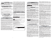
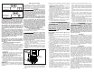
3. Set the depth of drive adjustment to the middle of its
range.
4. Reload fastener strip according to "Installing Fastener
Strips".
Set to
middle of
range
5. Begin testing the depth of drive by driving a test fas-
tener into the same type of workpiece material used
for the actual job using an air pressure of 90-95 psi.
6. Raise or lower the air pressure to fi nd the lowest
setting that will drive the fastener consistently. Do
not exceed 120 psi.
NOTE: It may be possible to achieve the desired
depth with air pressure adjustments alone. If fi ner
adjustments are needed, use the depth of drive
adjustment.
7. To fi ne-tune the depth of drive, disconnect the air
supply and lay the tool on its side and point the nose
of the tool away from yourself and others. Remove
fastener strip. Turn the depth selector left or right to
increase or decrease the driving depth.
8. Reload fastener strip according to "Installing Fastener
Strips".
9. Drive a test fastener and repeat step 7 and 8 until
desired depth is reached.
REQUIRED DAILY TESTING
WARNING
To reduce the risk of injury to your-
self and others, test the tool before
beginning work each day or if the tool is dropped,
received a sharp blow, been run over, etc. Complete
the following checklist IN ORDER. If the tool does
not work as it should, contact a MILWAUKEE service
facility immediately.
Always point tool away from yourself and others.
1. Disconnect the air supply from the tool and remove
fastener strip.
2. Check all screws, bolts, nuts, and pins on the tool.
Any loose fasteners must be tightened.
3. Pull back the fastener pusher on the magazine (to
override the Reload Indicator) and press the work-
piece contact against a workpiece. It must move
smoothly.
4. With the workpiece contact pressed against the
workpiece, pull the trigger. It must move smoothly.
5. Connect the air supply (at 70 psi) to the tool. DO NOT
load a fastener strip.
6. Select the Single Sequential Actuation Operation. Air
must not leak from the tool.
Without pulling the trigger, pull back the fastener
pusher on the magazine (to override the Reload
Indicator) and press the workpiece contact against
a workpiece. The tool must not operate.
Holding the workpiece contact away from the work-
piece, pull back the fastener pusher on the magazine
(to override the Reload Indicator). Pull and hold the
trigger for 5 seconds. The tool must not operate.
Continue to pull and hold the trigger and push the
workpiece contact against a workpiece. The tool must
not operate.
Without pulling the trigger, pull back the fastener
pusher on the magazine (to override the Reload
Indicator) and press the workpiece contact against
a workpiece. Pull the trigger. The tool must operate.
Release the trigger. The driver must move up.
7. Select the Contact Actuation Operation.
Holding the workpiece contact away from the work-
piece, pull back the fastener pusher on the magazine
(to override the Reload Indicator) and pull the trigger.
The tool must not operate.
Continue to pull and hold the trigger and push the
workpiece contact against a workpiece. The tool must
operate.
8. If all previous tests work properly, set the tool for your
work. Select the operation and load fastener strips.
9. Set the depth of drive according to the "Setting the
Air Pressure and Depth of Drive" section.
10. If all tests operate properly, the tool is ready for use.
Repeat these tests before use each day or if the
tool is dropped, received a sharp blow, been run
over, jammed, etc.
MAINTENANCE
WARNING
To reduce the risk of injury, use only
identical replacement parts recom-
mended by the manufacturer. Tool service must be
performed only by qualifi ed repair personnel. Al-
ways wear safety goggles or glasses with side
shields when servicing tools. Disconnect tool from
air supply before servicing.
Cleaning
Clean dust and debris from tool vents. Keep tool handles
clean, dry and free of oil or grease. Use only mild soap
and a damp cloth to clean the tool, since certain clean-
ing agents and solvents are harmful to plastics and
other parts. Some of these include gasoline, turpentine,
lacquer thinner, paint thinner, chlorinated cleaning sol-
vents, ammonia and household detergents containing
ammonia. Never use fl ammable or combustible solvents
around tools.
Lubrication
Frequent, but not excessive, lubrication is required
for best performance. Oil added through the air line
connection will lubricate the internal parts. Do not use
detergent oil, WD-40, transmission fl uid, motor oil, or
other lubricants not specifi cally designated as air tool
lubricant. These lubricants will cause accelerated wear
to the seals, o-rings and bumpers in the tool, resulting
in poor tool performance and frequent maintenance.
Cold Weather Operation
For cold weather operation, near and below freezing,
the moisture in the air line may freeze and prevent
tool operation. Use an air tool lubricant or permanent
antifreeze as a cold weather lubricant in the air line.
Do not store tools in a below-freezing environment. Ice
or frost could form on the tools' operating valves and
mechanisms, causing tool failure.
Air Supply-Pressure and Volume
Air volume is as important as air pressure. The air vol-
ume supplied to the tool may be inadequate because
of undersized fi ttings and hoses, or from the effects
of dirt and water in the system. Restricted air fl ow will
prevent the tool from receiving an adequate volume
of air, even though the pressure reading is high. The
results will be slow operation or reduced driving power.
Before evaluating tool problems for these symptoms,
trace the air supply from the tool to the supply source
for restrictive connectors, low points containing water
and anything else that would prevent full volume fl ow
of air to the tool.