
Use and Care Manual


3
SYMBOLOGY
Hertz
Amps
Volts
Alternating Current
Warning - Consult the operator's
manual for additional safety
information.
Read Operator's Manual
Power Tool Outlet
Intertek Standard
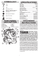
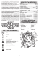
FUNCTIONAL
DESCRIPTION
7
5
4
3
6
2
1. Handle
2. Hose hook
3. Power switch
4. Speed control
5. Power tool socket
6. Inlet tting
9
7. Castors
8. Tank
9. Latches
10. Head
11. Accessory positions
10
11
8
2
1
SPECIFICATIONS
Cat. No. ..................................................... 8960-20
Input Volts .................................................... 120 AC
Input Amps...........................................................12
Input Hertz ......................................................50/60
Input Watts ......................................................1440
Vacuum Power .................................. 890 W / 7.4 A
Ingress Protection............................................IPX4
Max Output Watts ..............................................550
Max Output Amps ...............................................4.6
Tank Capacity gallons............................................8
Weight ..............................................36 lb (16.3 kg)
Air Flow cubic feet per minute ...........................148
Hose Diameter..............................................36 mm
HEPA Filter ...........................................49-90-1952
Main Filter ............................................. 49-90-1953
Plastic Dust Bag - 5PK ......................... 49-90-1954
Fleece Dust Bag - 5PK ......................... 49-90-1955
Power Tool Adapter .............................. 49-90-1957
Hose Sleeve ......................................... 49-90-1958
Hose Clip Adapter................................. 49-90-1959
Dust Extractor Adapter ......................... 49-90-1960
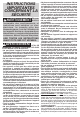
GROUNDING
INSTRUCTIONS
This appliance must be grounded. If it should mal-
function or breakdown, grounding provides a path
of least resistance for electric current to reduce the
risk of electric shock. This appliance is equipped with
a cord having an equipment-grounding conductor
and grounding plug. The plug must be inserted into
an appropriate outlet that is properly installed and
grounded in accordance with all local codes and
ordinances.
WARNING
Improper connec-
tion of the equip-
ment-grounding conductor can result in
a risk of electric shock. Check with a
qualied electrician or service person if
you are in doubt as to whether the outlet
is properly grounded. Do not modify the
plug provided with the appliance - If it
will not t the outlet, have a proper out-
let installed by a qualied electrician.
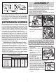
This appliance is for use on a nominal 120-volt circuit,
and has a grounded plug that looks like the plug il-
lustrated in sketch A. A temporary adapter that looks
like the adapter illustrated in sketches B and C may
be used to connect this plug to a 2-pole receptacle
as shown in sketch B if a properly grounded outlet
is not available. The temporary adapter should be
used only until a properly grounded outlet (sketch A)
can be installed by a qualied electrician. The green
colored rigid ear, lug or the like extending from the
adapter must be connected to a permanent ground
such as a properly grounded outlet box cover. When-
ever the adapter is used, it must be held in place by
a metal screw.