
Use and Care Manual


6 7
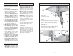
The grounding prong in the plug is connected
through the green wire inside the cord to
the grounding system in the tool. The green
wire in the cord must be the only wire con-
nected to the tool's grounding system and
must never be attached to an electrically
“live” terminal.
Your tool must be plugged into an appropri-
ate outlet, properly installed and grounded in
accordance with all codes and ordinances.
The plug and outlet should look like those
in Figure A.
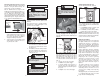
Double Insulated Tools:
Tools with Two Prong Plugs
Tools marked “Double Insulated” do not
require grounding. They have a special
double insulation system which satisfies
OSHA requirements and complies with
the applicable standards of Underwriters
Laboratories, Inc., the Canadian Standard
Association and the National Electrical
Code. Double Insulated tools may be used
in either of the 120 volt outlets shown in
Figures B and C.
Grounded Tools:
Tools with Three Prong Plugs
Tools marked “Grounding Required” have a
three wire cord and three prong grounding
plug. The plug must be connected to a prop-
erly grounded outlet (See Figure A). If the
tool should electrically malfunction or break
down, grounding provides a low resistance
path to carry electricity away from the user,
reducing the risk of electric shock.
Fig. B
Fig. C
Fig. A
Improperly connecting the grounding
wire can result in the risk of electric
shock. Check with a qualifi ed electri-
cian if you are in doubt as to whether
the outlet is properly grounded. Do
not modify the plug provided with
the tool. Never remove the grounding
prong from the plug. Do not use the
tool if the cord or plug is damaged.
If damaged, have it repaired by a
MILWAUKEE service facility before
use. If the plug will not fi t the outlet,
have a proper outlet installed by a
qualifi ed electrician.
GROUNDING
WARNING
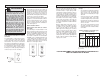
Cat. No.
9070-20
9072-20
9072-22
9092-20
9096-20
Quick Change Auger Bits
1-1/2"
1-1/2"
1-1/2"
1-1/2"
1-1/2"
Quick Change Chuck Capacities*
Selfeed Bits
2-9/16"
2-9/16"
2-9/16"
2-9/16"
2-9/16"
* Only for use with the 7/16" or 5/8" Hex Quick Change chuck, stan-
dard equiptment on the 9092-20 (7/16") and 9096-20 (5/8"), optional
accessory (Cat. No. 48-66-0061) on other models.
Double Insulated
Symbology
Volts Alternating Current/
Direct Current
Impacts per Minute
Under Load (IPM)
Amperes
Volts Alternating Current
Mexican Approvals
Marking
Underwriters
Laboratories, Inc.,
United States and Canada
Impacts Per
Minute
2600
2600
1000-2600
1000-2600
2500
1000-2600
1000-2600
Cat.
No.
9070-20
9071-20
9072-20
9072-22
9075-20
9092-20
9096-20
Average Torque
Output
300 ft-lbs.
300 ft-lbs.
100-300
ft-lbs.
100-300
ft-lbs.
380 ft-lbs.
100-315
ft-lbs.
100-315
ft-lbs.
Volts
120 AC/DC
120 AC/DC
120 AC Only
120 AC Only
120 AC/DC
120 AC Only
120 AC Only
Specifi cations
A
7
7
7
7
7
7
7
Drive
Shank
1/2"
1/2"
1/2"
1/2"
3/4"
7/16" Hex
5/8" Hex
No Load
RPM
1800
1800
600-1800
600-1800
1750
600-1800
600-1800