
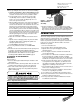
Product Manual

Chain Replacement with No Chain in Hoist
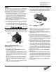
Refer to Figures 4 and 5.
1. DISCONNECT HOIST FROM POWER SUPPLY and move
hoist to a work table. Remove the electrical cover, electrical
panel and the electric brake assembly.
2. Detach the chain stripper from the bottom of the hoist.
3. Insert the new chain between the load sheave and the chain
guide. Feed the chain into the hoist by manually turning the
brake hub. Allow about 15" of chain below the hoist on the
slack end. Be sure the welds of the upstanding links are out
away from the load sheave and that proper orientation is
observed for attachment of the slack end. Also be sure the
load hook assembly (if already attached to the chain) is
toward the center of the hoist or to your right looking from
the transmission end.
4. Reinstall the chain stripper (with the chain anchor on double-
chained hoists, See Figure 4) observing proper chain
alignment and avoiding any twist in the chain.
5. Follow steps 11 through 14 in previous section, CHAIN
REPLACEMENT WITH CHAIN IN HOIST, to complete the
chain replacement procedure.
NOTE: Inspect chain guides and load sheave for wear,
replace as needed.
LIMIT SWITCH ADJUSTMENT
IMPORTANT: Before placing hoist in operation, check the limit
switch adjustment. Limit switches are provided to protect the
hoist against damage resulting from overtravel or to allow
setting the hook travel within the factory-set limits of travel. For
easy identification and association with the proper direction of
travel, the upper and lower limit switch adjusting nuts are color-
coded gold and silver respectively. Each limit nut has 10 slots
for fine adjustment, and the increment of adjustment is such
that one slot is equivalent to approximately one link of chain
travel. Movement of the limit switch nuts toward or away from
each other increases or decreases the hook travel respectively.
Care should be exercised when adjusting either limit of travel.
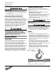
Adjusting Upper Limit (Gold Nut)
Refer to Figure 3.
1. Suspend the hoist. For single-chained models raise the load
block until there is a minimum clearance of 2" from the hoist
housing and the top of the block. Double-chained models
require a minimum clearance of 1" from the chain support to
the top of the load block.
2. DISCONNECT HOIST FROM POWER SUPPLY and
remove the electrical cover.
3. With a screwdriver, pry the spring guide plate out of the slots
in the limit switch nuts.
4. Turn the slotted gold nut toward its limit switch until the
switch “clicks” then turn two slots farther. Release the spring
guide plate and be sure it slips back into the slots in both
limit switch nuts. Do not disturb the silver slotted nut if it has
been set previously.
Adjusting Lower Limit (Silver Nut)
Refer to Figure 3.
1. Suspend the hoist. Carefully lower the load block to a point
where the slack-end loop of the chain hangs down 6" or
more from the hoist housing (or the limit desired in any
particular application allowing the minimum 6"). There
should be a minimum clearance of 1½" between the chain
stop and the bottom of the hoist.
2. DISCONNECT HOIST FROM POWER SUPPLY and
remove the electrical cover.
3. With a screwdriver, pry the spring guide plate out of the slots
in the limit switch nuts.
4. Turn the slotted silver nut toward its limit switch until the
switch “clicks,” then turn two slots farther. Release the spring
guide plate and be sure it slips back in the slots in both limit
switch nuts. Do not disturb the gold slotted nut if it has been
set previously.
Check Both Upper and Lower Limits
1. Connect the hoist to the power supply. Be sure the green
ground wire is properly grounded .
2. Check load hook direction (See INSTALLATION 2-c, page 5).
3. Carefully raise load block to upper limit and observe if it
stops automatically at desired level. Do not allow load block
to run into hoist housing — this will damage the hoist.
Maintain a minimum clearance of 2" from the hoist housing
and the top of the load block on single-chained models and
1" from the chain support to the top of the load block on
double-chained models.
4. Carefully lower load block to lower limit and observe if it
stops automatically at the desired level. Do not allow slack-
end loop of chain to become taut against hoist housing. This
will damage the hoist. There should be a minimum clearance
of 1½" between the chain stop and the bottom of the hoist.
5. If upper and lower limits operate satisfactorily, hoist is ready
for use. If they are not as desired, repeat adjustment.
BRAKE
Properly adjusted, this brake will release promptly when
energized. It is capable of both smoothly stopping and securely
holding the rated capacity of the hoist. If the hoist develops
either undesirable over-travel after the pushbutton is released
(this condition is most noticeable in the lowering direction) or
hesitates to lift the load promptly when the pushbutton is
depressed (this condition is most noticeable in the hoisting
direction), the brake should be adjusted.
8
Milwaukee Electric Tool Corporation
13135 West Lisbon Road
Brookfield, Wisconsin 53005
TEL: (800) 729-3878
There are wires running through the hoist. Carefully
ease the hoist sections apart. Do not jerk them apart.
If the wires running to the limit switches are ever
disconnected for any purpose, be sure to replace
wires in accordance with the correct wiring diagram
(See WIRING DIAGRAMS, page 12).