
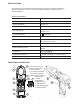
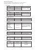
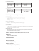
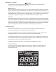
Specifications


9
symbol to indicate the software forced zero is disabled and the actual
reading is now displayed so the operator can adjust the real AD zero. Wait
around 1 minute the reading will stop falling and the operator can adjust
VR2 to null the number. Check the adjusting result stay at zero and turn
the unit off to finish the adjusting.
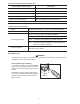
(2) Turn the unit off. Press and hold “ + ” keys and turn the function
dial to range “ ” then push “°F/°C” button
within 2 sec. The LCD will blink
“INRUSH” symbol. Input 220uF signal to the terminal then press “ ”
button to write the calibration data into the unit.
(3) Continue from note (2). Press “ ” button to switch unit to 4000
uF range.
Input 2200uF signal to the terminal then press “ ”
button to write the
calibration data into the unit. Check
220uF and 2200uF again. If reading
is correct, turn off the unit to complete the calibration procedure.
(4) Turn the unit off. Press and hold “ + ” buttons and turn the function
dial to
range “ ” then press “°F/°C” button within 2 sec. The LCD will blink
“ZERO” symbol. Input 0mV to the input terminals then press “ ” button to
write in the calibration data.
(5) Continue process in note (4). Input 16.395mV to the input terminals then
press “ ” to write in the calibration data.
(6) Continue process in note (5). Press “ ” button and the LCD will blink
“ ” symbol. Input 0°C signal
to the input terminals and press “ ”
button
the write in the calibration data. Check the reading. If the reading
is correct,
turn the unit off to complete the process.
Ω
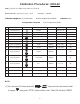
Calibration Procedures 2238-20 - continued