
Jig Saw OPERATOR'S MANUAL


8 9
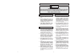
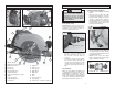
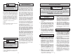
FUNCTIONAL DESCRIPTION
7
11
5
4
1. Tilt-Lok
™
handle
2. Handle lever release button
3. Handle release lever
4. Bevel scale
5. Bevel pointer
6. Bevel adjusting lever
7. Spindle lock button
8. Depth setting gauge (not shown)
9. Trigger
10. C
ord release button
11. Depth adjusting lever
12. Front handle
19
18
17
15
20
14
13
12
1
21
22
Cat. No. 6394
2
3
9
6
16
10
8
13. Sight line
14. Rip fence slot
15. Lower guard
16. Blade fl ange
17. Blade bolt
18. Blade
19. Shoe
20. Lower guard lever
21. Upper guard
22. Positive-Lok
®
cord
(Cat. No. 6394 only)
WARNING
TOOL ASSEMBLY
To reduce the risk of injury, alway
unplug tool before attaching or
removing accessories or making
adjustments. Use only specifi cally
recommended accessories. Others
may be hazardous.
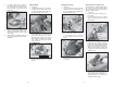
Removing and Replacing Positive-Lok
®
Cords (Cat. No. 6394)
MILWAUKEE’S exclusive Positive-Lok
®
Cords provide instant fi eld replacement or
substitution. The Positive-Lok
®
feature se-
cures the cord fi rmly to the tool.
1. To remove the Positive-Lok
®
Cord,
push the cord release button in the
direction shown and turn the cord
nut 1/4 turn to the left. Pull the
cord out.
2. To replace the Positive-Lok
®
Cord, align
the connector keyways and push the
connector in as far as it will go. Turn the
cord nut 1/4 turn to the right to lock. The
cord release button will click back into
place.
Selecting Blade
Always use sharp blades. Dull blades tend
to overload the tool and increase the chance
of KICKBACK (see "Operation"). Only use
blades with a maximum safe operating
speed greater than the no load RPM marked
on the tool's nameplate. Read the blade
manufacturer's instructions before use.
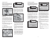
3. Slide the lower guard lever up to raise
the lower guard. Remove the blade from
the spindle. Always clean the spindle,
upper guard and lower guard to remove
any dirt and sawdust.
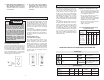
NOTE: Do not remove inner blade
fl ange. Larger diameter of inner fl ange
(Fig. 3) should face the blade.
Fig. 2
Cord release button
Fig. 1
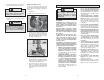
Installing and Removing Blades
1. Unplug tool before installing or removing
blades.
2. Place the saw on a fl at surface with
the blade facing upwards. To remove
the bolt from the spindle, push in the
spindle lock button. While holding in
the spindle lock button, use the wrench
provided with the tool to turn the bolt
counterclockwise (Fig. 2). Remove the
bolt and outer blade fl ange.
2
1
Bolt
Outer fl angeInner fl ange
Spindle
Fig. 3