
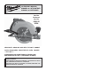
Jig Saw OPERATOR'S MANUAL


14 15
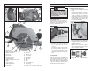
General Operation
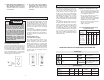
Always clamp the workpiece securely on a
saw horse or bench (Fig. 13). See “APPLICA-
TIONS” for the correct way to support your
work in different situations.
1. Draw a cutting line. Place the front of
the shoe on the edge of the workpiece
without making blade contact. Hold the
Tilt-Lok™ handle with one hand and the
front handle with the other (Fig. 14).
Fig. 13
Fig. 14
5. If the saw binds and stalls, maintain
a fi rm grip and release the trigger im-
mediately. Hold the saw motionless in
the workpiece until the blade comes to
a complete stop.
6. After fi nishing a cut, be sure the lower
guard closes and the blade comes to a
complete stop before setting the saw
down.
Electric Brake (Cat. No. 6394)
Select models feature an electronic brake.
The brake engages when the trigger is re-
leased, causing the blade to stop and allow-
ing you to proceed with your work. Generally,
the saw blade stops within two seconds.
However, there may be a delay between
the time you release the trigger and when
the brake engages. Occasionally the brake
may miss completely. If the brake misses
frequently, the saw needs servicing by an
authorized MILWAUKEE service facility. The
brake is not a substitute for the guard, and
you must always wait for the blade to stop
completely before removing the saw from the
workpiece. The correct brush grade must be
used for proper operation of the brake. Use
only the correct MILWAUKEE replacement
brushes when servicing the tool.
Troubleshooting
If the blade does not follow a straight line:
• Teeth are dull. This is caused by hitting a
hard object such as a nail or stone, dull-
ing teeth on one side. The blade tends to
cut to the side with the sharpest teeth.
• Shoe is out of line or bent
• Blade is bent
• Rip fence or guide is not being used
If the blade binds, smokes or turns blue
from friction:
• Blade is dull
• Blade is on backwards
• Blade is bent
• Blade is dirty
• Workpiece is not properly supported
• Incorrect blade is being used
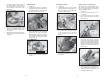
2. Line up the sight line with your cutting
line. Position your arms and body to
resist KICKBACK. Pull the trigger, allow-
ing the motor to reach full speed before
beginning to cut.
3. While cutting, keep the shoe fl at against
the workpiece and maintain a firm
grip. Do not force the saw through the
workpiece. Forcing a saw can cause
KICKBACK.
4. If making a partial cut, restarting in
mid-cut or correcting direction, allow
the blade to come to a complete stop.
To resume cutting, center the blade in
the kerf, back the saw away from cutting
edge a few inches, pull the trigger and
re-enter the cut slowly.
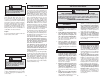
APPLICATIONS
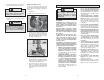
Selecting Tilt-Lok™ Handle Positions
The Tilt-Lok™ handle is a feature which
allows the user to adjust the angle of the
handle for optimum cutting positions. The
Tilt-Lok™ handle has eight (8) detents
which allow the handle to snap into position
(Fig. 15). See “Adjusting Tilt-Lok™ Handle”
for instuctions on adjusting the handle. Re-
fer to the chart below for suggested handle
positions.
* These are only suggested positions; the actual optimum cutting position
may vary depending on the actual application and user preference.
APPLICATION SUGGESTED TILT-LOK POSITIONS*
For cuts made at or near
waist level
Handle in lower positions (Fig. 16) allows for more leverage
when pushing the saw through the workpiece.
For shallow cuts made at
or near waist level
Handle in lower positions allows the user to apply increased
downward force during shallow cuts.
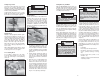
For cuts made below the
waist, as in fl ooring ap-
plications
Handle in higher positions (Fig. 17) reduce the amount of
“bending over” by the user. Higher handle positions allow
the user to apply an increased downward force on the saw.
For cuts made overhead,
as in ceiling applications
Handle in higher positions reduce the amount of extended
reach by the user for overhead cuts. Higher handle posi-
tions allow the user to apply an increased upward force on
the saw.
Fig. 16
Fig. 15
WARNING
To reduce the risk of injury, wear
safety goggles or glasses with side
shields. Unplug the tool before
changing accessories or making
adjustments.
Fig. 17