
Bulletin


4
PAGE
4939 5445 01
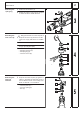
Removing
the lever
1
Pull the adjusting plate (4) from the pin (2)
of the lever (1).
2
Squeeze together the spring (5) at the bot-
tom side of the lever (1) and remove the
lever from the gear box cover.
3
Remove the O-ring (3).
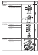
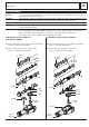
Combined
drill/chisel
hammer:
Removing
the spindle
1
Loosen the spindle assembly (1) by turn-
ing it slightly and pull it off from the front of
the gear box (direction of arrow).
☞
In case of stiffness, lightly tap the gear
box (2) with a plastic hammer – the
spindle (1) will be released in direction
of arrow.
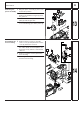
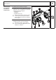
Chisel
hammer:
Removing
the spindle
1
Loosen the seal ring (3) with circlip pliers
from the spindle groove.
2
Loosen the spindle assembly (5) by turn-
ing it slightly and pull it off from the front of
the gear box (direction of arrow).
☞
In case of stiffness, lightly tap the gear
box (4) with a plastic hammer – the
spindle (5) will be released in direction
of arrow.
3
Remove the seal ring (3), the attach-
ment ring (2) and the O-ring (1) from the
gear box (4).
1
2
3
5
4
9
1
2
10
321
4
5
10