
Bulletin


7
PAGE
4939 5445 01
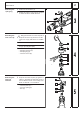
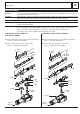
Disassembling
the armature
1 Loosen three Allen screws (8) from the
bearing end plate (7) and pull the
complete armature assembly (B) with
the bearing end plate (7) from the
gear box (1).
2 Remove the seal (2) from the gear box (1).
3 Insert the pin-type face spanner (service
tool) (3) into the seal ring (4) and remove
the seal ring (4) counter-clockwise.
Remove the bearing end plate (7).
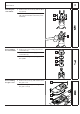
4 Remove the locking ring (5) from the
bearing end plate (7) and press out the
bearing (6).
5 Separate the fan (9) from the armature (B)
with the forcing discs (A).
6 Remove the rubber sleeve (D) and press
off the bearing (C).
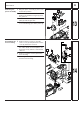
Detaching the
crank wheel
1 Remove the following parts from the gear
box (4):
– crank wheel (5)
– disc (8)
– axial bearing (9)
– disc (B).
2 Pull the needle bearings (6) and (7) with
the interior extractor (A) from the crank
wheel (5).
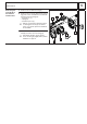
3 Combined drill/chisel hammer:
Additionally remove the safety clutch (1)
from the gear box (4). Pull the needle
bearings (2) and (3) with the interior
extractor (A) from the gear box (4).
☞
The chisel hammer does not have
a safety clutch (1) and needle bear-
ings (2) and (3)!
9
2
3
4
5
6
8
7
A
B
C
D
1
15
1
2
3
4
5
6
7
9
B
A
8
16