PAGE 1 4939 5445 01 Special Tools Require ■ ■ ■ ■ ■ ■ ■ Important! ■ Before beginning the maintenance work, perform an initial check with a high voltage test according to VDE (see chapter Electrical and Mechanical Test Instructions).
PAGE 2 4939 5445 01 Removing the spring ring 1 Remove both retainers (1). 2 Slightly spread the spring ring (2) and pull 1 it off the machine towards the front. 3 2 1 Detaching the end cover cap ☞ Bring the machine in a vertical position. 1 Depress the sleeve (2) and lever off the end cover cap (1) with aid of a screwdriver. 2 Remove the sleeve (2). 3 Loosen the spring ring (3) with aid off 1 Seeger special pliers (A2).
PAGE 3 4939 5445 01 Detaching the seal retainer 1 Remove the four screws (1) with an Allen key (5 mm). 2 Turn the seal retainer (2) 45° and expel it 1 with a plastic hammer from below (see illustration). 2 45° 6 2 Disassembling the seal retainer 1 Remove the outer seal ring (2) from the seal retainer (1). 1 2 Remove the inner seal ring (3) from the seal retainer (1). 3 Remove the Seeger circlip ring (4) from 2 the spindle.
PAGE 4 4939 5445 01 Removing the lever 1 Pull the adjusting plate (4) from the pin (2) 1 2 3 of the lever (1). 2 Squeeze together the spring (5) at the bottom side of the lever (1) and remove the lever from the gear box cover. 3 Remove the O-ring (3). 9 5 4 Combined drill/chisel hammer: 1 Loosen the spindle assembly (1) by turning it slightly and pull it off from the front of the gear box (direction of arrow).
PAGE 5 4939 5445 01 Disassembling the spindle 1 Remove the thrust collar (1) from the spindle (4). Remove the O-ring (2) from the thrust collar (1). 2 1 2 Expel the percussion body (5) from the spindle (4) by tapping it lightly with a plastic hammer. Remove the O-ring (6) from the percussion body (5). 3 Remove the Seeger circlip ring (3) from 5 the spindle with Seeger circlip pliers.
PAGE 6 4939 5445 01 Removing the piston assembly 1 Bring the piston assembly (5) in the back 2 dead center position. 1 2 Combined drill/chisel hammer: Remove the spindle bevel gear (3) from the gear box. 3 Remove the set collar (1) and the locking 5 plate (2) from the gear box. 4 13 4 Remove the piston assembly (5) upwards. Loosen the O-ring (4) from the piston (5).
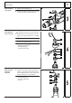
PAGE 7 4939 5445 01 Disassembling the armature 1 Loosen three Allen screws (8) from the bearing end plate (7) and pull the complete armature assembly (B) with the bearing end plate (7) from the gear box (1). 7 2 Remove the seal (2) from the gear box (1). 3 Insert the pin-type face spanner (service 6 5 tool) (3) into the seal ring (4) and remove the seal ring (4) counter-clockwise. Remove the bearing end plate (7).
PAGE 8 4939 5445 01 Removing the gear cover 1 Loosen two screws (1) and remove the gear cover (2). ☞ The exposed plane surface serves only for manufacturing the gear box and has no other function! 17 2 1 Disassembling the electronic component 1 Remove the four screws (1) from the 1 2 handle and remove the handle half (2). 2 To branch off the mains cable, remove 4 3 two screws (4) from the switch. 3 Remove the screw (5) from the strain relief (6) and remove the mains cable (7).
PAGE 9 4939 5445 01 Removing the anti-vibration mechanism and the field 1 Remove the air deflector ring (5). 2 Remove the screw (4). Detach the follow- 3 ing parts of the anti-vibration mechanism from the motor housing (8): – thrust piece (1) – spring (2) – transition piece (3). ☞ Danger of injury! Pay attention when loosening the screw (4): the thrust piece (1) is under pressure and must be steadied! 2 1 19 4 3 Loosen two screws (7) and remove the 8 field (6) from the motor housing (8).
PAGE 10 4939 5445 01 Maintenance General It is recommended that maintenance be performed on the machine at regular intervals or when the carbon brushes switch off at the latest. Cleaning Clean all parts – with the exception of the electrical parts – with cold cleaning agent. Caution! No cleaning agent should penetrate into the bearing. Clean the electrical parts with a dry brush. Check for wear Check the disassembled parts for wear (visual inspection) and replace worn parts.
PAGE 11 4939 5445 01 Lubrication: Combined drill/chisel hammer Put approx.
PAGE 12 4939 5445 01 Lubrication: Chisel hammer Put approx.
PAGE 13 4939 5445 01 Sequence and torques of the screws: B 5 6 7 1 5 3 7 1 6 2 4 A J 2 G 3 M 4 D N C K F L E I H Torques Bearing cover 4 Nm A 1) Top gear cover 4.5 Nm B 1) Gear cover 3 Nm C Seal retainer 12 Nm D 1) Motor housing 13 Nm E 1) Service cover 1.3 Nm F Handle 3 Nm G Field 2 Nm H Anti-vibration mechanism 3 Nm I Round nut 16 Nm J Cable clip 1.3 Nm K Carbon brush holders 1.3 Nm L Connection wires switch 0.
PAGE 14 4939 5445 01 Assembly Mounting the anti-vibration mechanism and the field 1 Insert the field (6) into the motor hous- 3 ing (8) and fix it with two screws (7) (torque = 2 Nm). 2 1 2 Insert the following parts of the antivibration mechanism into the motor housing (8): – transition piece (3) – spring (2) – thrust piece (1). c 4 e 3 Fix the anti-vibration mechanism with the 1 f d 8 screw (4) (torque = 3 Nm). 4 Insert the air deflector ring (5) into the motor housing (8).
PAGE 15 4939 5445 01 Wiring in the machine red: field – carbon brush holder white: carbon brush holder – carbon brush blue: field – electronic black: electronic – switch red: field – carbon brush holder white: carbon brush holder – carbon brush red: field – electronic brown: carbon brush – electronic (carbon brush cutoff) Wiring in the handle brown: mains cable to switch black: switch – electronic blue: mains cable to switch
PAGE 16 4939 5445 01 Mounting the gear cover 1 Fix the gear cover (2) with two screws (1) onto the gear box (torque = 3 Nm). 3 2 1 Mounting the crank wheel 1 Combined drill/chisel hammer: Press the needle bearings (2) and (3) flush into the gear box (4). ☞ 5 The names on the needle bearings must be visible! 6 2 Press the needle bearings (6) and (7) 1 flush into the crank wheel (5).
PAGE 17 4939 5445 01 Assembling the armature 1 Press on the bearing (B) and put on the rubber sleeve (C). 2 See illustration below: Press the fan (9) onto the indicated bearing measure. Afterwards, apply some instant glue (e. g. Sicomet) on the armature shaft (marked with arrows). ☞ The distance between the upper side of the fan (9) and the lower side of the bearing (B) must be 159 mm (bearing measure) according to the below illustration.
PAGE 18 4939 5445 01 Mounting the motor housing 1 Apply locking agent on the four screws (4). Insert the gear box with the armature (5) into the motor housing (6) and fix them with the four screws (4) cross-wise (torque = 13 Nm). 1 2 2 Insert the carbon brushes (3) on both sides and connect them. 3 Insert the service cover (1) slanted and fix 6 it with two screws (2) (torque = 1.3 Nm).
PAGE 19 4939 5445 01 Mounting the piston 1 Combined drill/chisel hammer: 1 Insert the spindle bevel gear (3) into the gear box. 2 2 Mount the O-ring (4) on the piston (5). 3 Insert the piston (5) into the set collar (1) 5 and the locking plate (2) and insert the assembly into the gear box: put the connecting rod of the piston (5) on the pin (6) of the crank wheel.
PAGE 20 4939 5445 01 Mounting the spindle 1 Mount the O-ring (3) on the percussion body (2). 2 Insert the percussion body (2) into the spindle (1). 3 2 1 Combined drill/chisel hammer: Inserting the spindle 1 Insert the complete spindle assembly (1) into the gear box (2) as far as it will go. ☞ ☞ The piston must grasp the rear end of the spindle! The spindle (1) gets the necessary lubrication when it is inserted into the gear box (2).
PAGE 21 4939 5445 01 Mounting the lever 1 Insert the O-Ring (3) into the opening of 6 the gear box cover (4). 1 2 Squeeze together the spring (6) at the bot- 2 3 tom side of the lever and insert it slantwise into the opening of the gear box cover (4), beginning at the two lugs (7). 3 Set the lever (1) to 0. 4 Mount the spring clip at the adjusting plate (5) on the pin (2) of the lever (1). 7 5 Set the lever (1) to the “chisel” setting res. 4 .
PAGE 22 4939 5445 01 Inserting the thrust collar 1 Mount the O-ring (2) on the thrust collar (3). 6 2 Insert the thrust collar (3) into the gear box (1) and push it over the spindle as far as it will go. ☞ ☞ Put the sleeve (service tool) (4) on the thrust collar (1). Push in the thrust collar (3) with light blows on the sleeve (4) until the locking ring (2) can be mounted in the gear box (1). 5 7 5 Both holes in the retaining ring (5) are tapered.
PAGE 23 4939 5445 01 Mounting the end cover cap 1 Mount the following parts: – interlock sleeve (6) – damping ring (5) – damping element (4). 1 2 Mount the spring ring (3) with aid 2 of the service tools mounting sleeve (4931 599 102) and mounting cone (4931 599 103): Illustration A: Put the spring ring (3) onto the conical part of the mounting cone (8). Illustration B: Depress the spring ring (3) with the smaller part of the mounting sleeve (9) about half way down the cone.
PAGE 24 4939 5445 01 Mounting the spring ring 1 Push the spring ring (2) over the machine from the front and mount both retainers (1). 1 2 18 1 Mounting the handle 1 Press together the retainers (2) on both sides and mount the handle (4). 1 2 Insert the screw (1) and screw down the knob (3). 19 2 3 4 Mounting the auxiliary handle 1 Screw down the auxiliary handle (1). 1 20 Test Run Electrical Test Test run the machine and pay attention to noises. Let the machine run-in.