
Operator's Manual


ACCURACY FIELD CHECK
NOTICE
Horizontal Height Accuracy
AB
30cm
20m
5
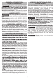
2. Turn the tool to ON and to Perpendicular
Level & Plumb Points Mode.
3. Direct the front laser beam against the nearest
wall A and allow to self-level. Mark the centre of
the laser cross on the wall (point I).
4.
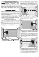
Rotate the tool 180° without changing the height,
allow it to self-level, and mark the centre of the
laser cross on the opposite wall B (point II).
A
180
B
5.
AB
30cm
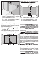
6. Adjust the height of the tool (using the tripod or
7.
by adding shims, if required) to align the laser
cross directly onto point II on wall B. Allow the
tool to self-level.
Rotate the tool 180° without changing the height,
allow it to self-level, and mark the center of the
laser cross on wall A (point III). Point III should
be aligned as vertically above or below point I on
wall A as possible.
A
B
B
180
d
8.
Perform the Accuracy Field Check
procedure immediately upon
unboxing of each new Laser Level and before
exposure to jobsite conditions. See "Accuracy
Field Check" for information. Should any
deviation from listed product accuracy be found,
please contact a MILWAUKEE
®
service facility.
Failure to do so could result in rejection of warranty
claim.
Securely mount the tool within 30cm of wall 'A' as
shown below.
1.
Ambient temperature gradients can impact laser
accuracy. For accurate and repeatable results, the
following procedure should be conducted with the
laser elevated off the ground and placed in the
centre of the working area.
Abusive treatment of the Laser Level, such as
excessive impacts from repeated or high drops,
can also lead to deviations in product accuracy.
Therefore, it is recommended to conduct the
Accuracy Field Check procedure after any impact
or before completing any critical jobs.
A free measuring distance of approximately 20m on
a firm surface between two walls or structures
(indicated as 'A' and 'B' below) is required for this
check.
It is also suggested to mount the Laser Level to an
appropriate tripod for easy adjustment.
Move the tool within 30cm of wall B. Allow the
laser to self level. Align the laser cross in the
general direction of point II on wall B.
The distance between points I and III on wall A is
the height deviation (d) of the tool. This distance
should not exceed 3.18mm (max.) at 10m
(12.72mm at 40m). For the Measuring distance of
2 x 20m = 40m, the maximum allowable deviation
(d) is: 40m x ±3.18mm ÷ 10m = ±12.72mm