
Operator's Manual


3
eyes, additionally seek medical help. Liquid ejected
from the battery may cause irritation or burns.
Do not use a battery pack or tool that is damaged or
risk of injury.
Do not expose
-
cessive temperature.
above 130°C (265°F) may cause explosion.
Follow all charging instructions and do not charge
the battery pack or tool outside the temperature
Charging im-
may damage the
SERVICE
repair person using only identical replacement
parts. This will ensure that the safety of the power
tool is maintained.
Never service damaged battery packs. Service
of battery packs should only be performed by the
manufacturer or authorized service providers.
SPECIFIC SAFETY RULES FOR
RATCHETS
Hold power tool by insulated gripping surfaces,
when performing an operation where the fastener
may contact hidden wiring. Fasteners contacting
a “live” wire may make exposed metal parts of the
power tool “live” and could give the operator an
electric shock.
Maintain labels and nameplates. These carry
important information. If unreadable or missing, contact
a MILWAUKEE
®
service facility for a replacement.
WARNING
Some dust created by power sanding,
sawing, grinding, drilling, and other
construction activities contains chemicals known to
cause cancer, birth defects or other reproductive
harm. Some examples of these chemicals are:
lead from lead-based paint
crystalline silica from bricks and cement and other
masonry products, and
arsenic and chromium from chemically-treated lumber.
Your risk from these exposures varies, depending on
how often you do this type of work. To reduce your
exposure to these chemicals: work in a well ventilated
area, and work with approved safety equipment, such
as those dust masks that are specially designed to
SPECIFICATIONS
Volts.............................................................. 12 DC
Battery Type .................................................M12™
Charger Type................................................M12™
Recommended Ambient
Operating Temperature ..........................0
o
C - 52
o
C
Cat. No. .................................................M12 FIR14
RPM ............................................................... 0-250
Torque Range ............................................0-54 Nm
Square Drive Anvil ............................................ 1/4"
Cat. No. .................................................M12 FIR38
RPM ............................................................... 0-190
Torque Range ............................................0-74 Nm
Square Drive Anvil ............................................ 3/8"
Cat. No. .................................................M12 FIR12
RPM ............................................................... 0-175
Torque Range ............................................0-81 Nm
Square Drive Anvil ............................................ 1/2"
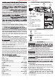
FUNCTIONAL DESCRIPTION
1. Paddle switch
2. Lock off switch
3. LED
4. 1/4" square drive anvil
5. Forward/Reverse toggle
6. Fuel gauge
7. Handle
8. 3/8" square drive anvil
9. 1/2" square drive anvil
5
4
6
2
3
1
7
Cat. No. M12 FIR14
Cat. No. M12 FIR12
9
Cat. No. M12 FIR38
8
SYMBOLOGY
Volts
Direct Current
No Load Revolutions per Minute (RPM)
Lock Off Switch
C
US
UL Listing for Canada and U.S.
ASSEMBLY
WARNING
Recharge only with the charger
-
manual supplied with your charger and battery.
Removing/Inserting the Battery
To remove the battery, push in the release buttons
and pull the battery pack away from the tool.
WARNING
Always remove battery pack before
changing or removing accessories.
To insert the battery, slide the pack into the body
of the tool. Make sure it latches securely into place.
WARNING
recommended for this tool. Others
may be hazardous.
Use only sockets and other accessories spe-
sockets and accessories might shatter or break
causing injury.
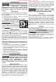
Attaching and Removing Accessories
These tools are intended only for use with accesso-
ries designed for impact tools. Other sockets could
shatter or break, causing injury.
1. Use only appropriate Square Drive Sockets.
2. To attach a socket or other accessory, align the
onto the tool.
3. To remove the accessory, pull the accessory off
the drive anvil.
For si
g
n-off review, sent 27 Apr. 2017