
Operator's Manual


4
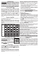
Menu Guide
To navigate throughout the menu guide , use the
arrow buttons
to modify settings. To set a
function within each category select the
OK
button.
Use exit button
to exit each page.
Description Function
Modes Add preset functions to a profile
setup units, target torque, and a
percentage range.
Saved Events Allow for grouping events and to
view recent history. (See "Saved
Events/Grouping" section.)
Grouping Organise events by saving to an
open group. (See "Saved Events/
Grouping" section.)
View Recent
History
Recall recent history from a previous
time frame.
Settings View sub categories within the set
-
tings function.
Units Select units; ft-lbs, in-lbs, Nm and
kg-cm
Sound &
Haptics
Change ON/OFF options to light,
sound and haptics.
Screen
Brightness
Select between Low, Medium and
High screen brightness modes.
Screen Display Select light or dark backlight display.
Language Change the language setting; be
-
tween English, French, Spanish, etc.
Rundown
Torque
Add a percentage to the total se-
lected torque. Tool will stop at or
near
the percentage allowing user
to hand tighten for full torque. (See
"Adjusting rundown torque")
About
General information for a certification
count and firmware
Certification
Count
Display the last certied date and
a count until the next certification is
required. (See "Certification" section
for more information.)
Firmware Displays firmware version and tool
part number.
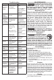
Modes
Use the modes function to set up a profile quickly
within a c
ouple of s
teps. Within
the modes option: set
up units, target torque and percentage range. Once
the mode is selected: apply, edit or delete a mode.
Saved Events / Grouping
Save events to use at a later date. Storing in a group
will make it easier to recall preset specifications. The
tool will not automatically save events. From the main
screen, use the left and right arrows
and select
the save button
. To open a group and include
saved events within the group. Press and hold the
save button
for 3 seconds.
ONE-KEY™
To learn more about the ONE-KEY™ function-
ality for this tool, please reference the Quick
Start guide included with this product or go to
onekey.milwaukeetools.com.au. To download
the ONE-KEY™ app, visit the App Store or Google
Play from your smart device.
SYMBOLOGY
Volts............................................................ 12V DC
Battery Type .................................................M12™
Charger Type................................................M12™
Coin Cell Battery...................................3V CR2032
RPM ............................................................... 0-100
Recommended Ambient
Operating Temperature ...................... -17°C to 51°C
Recommended Operating
Humidity Percentage ...................0% or up to 90%
Non-Condensing
Cat. No. ........................................ M12 ONEFTR38
Torque Range .........................................13-135Nm
Square Drive Anvil ............................................ 3/8"
Cat. No. ........................................ M12 ONEFTR12
Torque Range .........................................16-203Nm
Square Drive Anvil ............................................ 1/2"
ASSEMBLY
WARNING
Recharge only with the charger
specied for the battery. For spe-
cic charging instructions, read the operator’s
manual supplied with your charger and battery.
Removing/Inserting the Battery
To remove the battery, push in the release buttons
and pull the battery pack away from the tool.
WARNING
Always remove battery pack before
changing or removing accessories.
To insert the battery, slide the pack into the body
of the tool. Make sure it latches securely into place.
WARNING
Only use accessories specically
recommended for this tool. Others
may be hazardous.
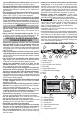
Battery Indicator
The battery indicator displays the amount of
charge left in the battery pack. The battery indicator
will stay lit during operation.
Charge the battery when battery indicator
is
shown. NOTE: Tool will shut o when the battery has
depleted.
WARNING
Use only sockets and other acces-
sories specifically designed for
use on this tool. Other sockets and accessories
might shatter or break causing injury.
Attaching and Removing Accessories
These tools are intended only for use with acces-
sories designed for torque wrenches. Other sockets
could shatter or break, causing injury.
1. Use only appropriate Square Drive Sockets.
2. To attach a socket or other accessory, align the
accessory with the drive anvil and push it firmly
onto the tool.
3. To remove the accessory, pull the accessory o
the drive anvil.
Regulatory Compliance mark (RCM).
This product meets applicable
regulatory requirements.
Volts
Direct Current
No Load Revolutions per Minute (RPM)
Read Operator's Manual
To reduce the risk of fire,
WAR
NIN
G
ADDITIONAL BATTERY SAFETY RULES
personal injury , and product damage due to a
circuit, never immerse your tool, battery pack or
charger in fluid or allow a fluid to flow inside them.
Corrosive or conductive fluids, such as seawater ,
certain industrial chemicals, and bleach or bleach-
containing products , etc., can cause a short circuit.
SPECIFICATIONS