
Operator's Manual


5
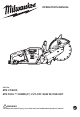
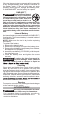
FUNCTIONAL DESCRIPTION
8
10
11
5
9
8. Bail handle
9. Water supply tube
10. Wheel guard handle
11. Spindle lock access
hole
12. Battery door button
13. Load indicator light
14. Hex wrench storage
1. ONE-KEY™
indicator
2. Water supply valve
4. Scrench storage
5. Rear handle
6. Trigger
7. Battery door
2
3
1
6
7
4
13
14
12
WARNING
Always remove battery pack before
ASSEMBLY
WARNING
Recharge
for
onl
the
y with
battery
th
.
e ch
For
arg
spe
er
-
manual supplied with your charger and battery.
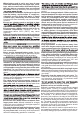
Removing/Inserting the Battery
To remove the battery, press the battery door but-
ton and open the battery door. Push in the release
buttons and pull the battery pack away from the tool.
1.
2.
To install
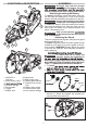
Spindle
bolt
Outer
Spindle
Wheel
changing or removing accessories.
To insert the battery, press the battery door button
and open the battery door. Slide the pack into the
body of the tool. Make sure it latches securely into
place. Close battery door.
WARNING
reco
Only use
mmended
accessorie
for thi
s
s tool. Others
may be hazardous.
Adjusting the Guard
This tool is shipped with a guard. Always use a guard
when operating this tool.
To adjust the guard,
push the wheel guard handle
forward or pull it back to move the guard to the de-
sired location. WARNING! Always adjust the guard
to provide the operator with maximum protection
while operating.
WARNING
T
operator should
o reduce the risk of injury
be instructed
, the
in
Use only the proper wheel made for this tool. DO
NOT USE ANY TYPE OF SAW BLADE. USE ONLY
TYPE "1" ABRASIVE and Diamond WHEELS.
3. While holding the spindle in place with the hex
wrench (1), install and tighten the spindle bolt
securely with the scrench (2).
1
2