OPERATOR'S MANUAL Cat. No. M18 FMS305 M18 FUEL™ 305mm (12") DUAL BEVEL COMPOUND SLIDING MITRE SAW W/ ONE-KEY™ WARNING To reduce the risk of injury, user must read and understand operator's manual.
•Dress properly. Do not wear loose clothing or jewelry. Keep your hair and clothing away from moving parts. Loose clothes, jewelry or long hair can be caught in moving parts. •If devices are provided for the connection of dust extraction and collection facilities, ensure these are connected and properly used. Use of dust collection can reduce dust-related hazards. •Do not let familiarity gained from frequent use of tools allow you to become complacent and ignore tool safety principles.
Do not expose a battery pack or tool to fire or •Cut only one workpiece at a time. Stacked multiple excessive temperature. Exposure to fire or workpieces cannot be adequately clamped or braced temperature above 130°C (265°F) may cause and may bind on the blade or shift during cutting. explosion. •Ensure the mitre saw is mounted or placed on a level, •Follow all charging instructions and do not charge the battery pack or tool outside the temperature face reduces the risk of the mitre saw becoming unstable.
SYMBOLOGY dust created by power sanding, WARNING Some sawing, grinding, drilling, and other Volts construction activities contains chemicals known to cause cancer, birth defects or other reproductive harm. Some examples of these chemicals are: •lead from lead-based paint •crystalline silica from bricks and cement and other masonry products, and •arsenic and chromium from chemically-treated lumber. Your risk from these exposures varies, depending on how often you do this type of work.
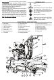
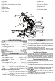
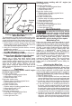
32. Hand stop 33. Wrench storage (not shown) 34. 6 mm Hex Wrench 35. Workpiece clamp sockets (2) 36. Spindle lock 37. Handle 38. Kickstand tip bar 24. Trigger 25. Trigger lock 26. Cut-line indicator switch (not shown) 27. Dust chute 28. Dust bag 29. Slide rail lock 30. Bevel knob 31. 0° stop pin 24 25 37 26 28 27 36 29 30 31 38 35 33 32 34 ASSEMBLY SPECIFICATIONS Cat. No. ............................................. M18 FMS305 Volts............................................................
Mounting the Mitre Saw 4. Press in the spindle lock and rotate the spindle/ blade until the lock engages. 5. Use the wrench to loosen and remove the left-hand thread blade bolt (clockwise). 6. To prevent the tool from sliding, falling or tipping from a raised work surface during operation, the saw should be mounted to a supporting surface such as a level, sturdy work table, bench, or mitre saw stand. Position the saw and workbench to allow adequate room for cross-cutting long workpieces.
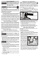
ADJUSTMENTS ays remove the battery pack WARNING Alw before changing accessories or Support of Longer Workpieces Longer workpieces need support along their full length. If you are using the saw on a level work bench, prop up the workpiece to a height of 76 mm (3”) ((2) 50 mm x 101 mm (2”x 4”) stacked flat) from the bottom of the saw feet. There are also many aftermarket work tables specifically designed for mitre saws that provide supports for all types of workpieces. making adjustments.
Adjusting the Fences Cut Line Indicator Every time the bevel or mitre angle settings are changed, make sure the fences are set correctly. Fences MUST: •Support the workpiece •Not interfere with the blade or lower guard •Be adjusted to keep hands out of the No Hand Zone To adjust the Fences 1. Remove battery pack. 2. Loosen the fence lock thumb screw. 3. Slide the fences side-to-side to the desired position to allow for a bevel or compound mitre cut.
Making a Sliding Cut (Cross Cut) •Wood - solid wood, plywood, particle board, MDF Wider workpieces can be cut using the sliding mechanism. Always use chop cut whenever possible. formica laminates, hardboard (masonite). •Plastics - PVC, CPVC, ABS, solid surfacing materials (such as Corian®), and other plastic materials. When cutting plastic, avoid overheating the blade and blade teeth to prevent melting the workpiece. •Nonferrous Metals - aluminum, brass, copper, and other non-ferrous materials.
Standard crown molding with 45° angles (set bevel angle to 0°) Left side, inside corner 1. Top edge of molding against fence 2. Mitre table set right 45° 3. Save left end of cut Right side, inside corner 1. Bottom edge of molding against fence 2. Mitre table set left 45° 3. Save left end of cut Left side, outside corner 1. Bottom edge of molding against fence 2. Mitre table set left 45° 3. Save right end of cut Right side, outside corner 1. Top edge of molding against fence 2. Mitre table set right 45° 3.
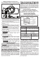
Squaring the Blade (90°) to the Table (0° Bevel) 5. Close the battery door and tighten the screw 1. Remove battery pack. securely. 2. ACCESSORIES 3. Move the bevel adjustment lever to the middle Use only recommended accessoposition and wedge in a tool (screw driver etc.) WARNING ries. Others may be hazardous. so the handle stay in the middle position. Move the saw head so that the bevel detent mechanism For a complete listing of accessories, go online to www.milwaukeetools.com.
WARRANTY - AUSTRALIA and NEW ZEALAND Please refer to Australian and New Zealand warranty supplied with tool. This warranty applies only to product sold in Australia and New Zealand. SERVICE - AUSTRALIA and NEW ZEALAND MILWAUKEE®prides itself in producing a premium quality product that is Nothing But Heavy Duty®. Your satisfaction with our products is very important to us! If you encounter any problems with the operation of this tool, please contact your authorised MILWAUKEE® dealer.