
Operator's Manual


5
8. Hand-tighten the collet nut.
9.
Installing/Removing Bases
during use, causing serious personal injury.
WARNING
securely, the bi
If the collet nut is not tightened
t may come out
WARNING
Pressing the macro adjustment button will cause
the motor housing to drop down, which may
cause personal injury or damage to the tool or
motor when pressing the button.
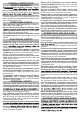
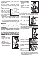
Fixed Base
3
1
2
Macro
adjustment
button
3.
4.
1. Open the quick release
lever. (1)
2
5.
Insert the tool into the
base. (3)
Release the button.
Close the quick release
lever.
reverse the procedure.
6. To remove the base,
1
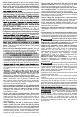
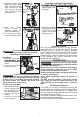
bit
Transfer
Spindle
lock
1
2
base. (2)
5. Insert the tool into the
2. Remove the collet nut
and install the transfer
bit.
3.
4. Open the quick release
lever. (1)
X
9.
10.
7. If the transfer bit does
not align, remove the
motor from the offset
base, rotate the transfer
bit slightly, and reinstall
the base.
8. Close the quick release
lever.
Insert the trimmer bit
into the collet until it bottoms out.
11. To set the depth of cut, insert the 3 mm hex
wrench into the micro adjustment set screw.
Rotate clockwise (-) or counterclockwise (+) to
reach the desired depth of cut.
Press and hold the spindle lock and use the 17
mm (11/16") wrench to securely tighten the collet
nut clockwise (or use the 11 mm (7/16") spindle
lock wrench to hold the spindle securely).
To reduce the risk of injury, DO
NOT use the trimmer if the quick
release lever does not hold the motor securely
in the base. If the quick release lever becomes
loose, secure the screw with a 3 mm hex wrench
to make a snug fit.
Press the macro
adjustment button on
the fixed base. (2)
Press and hold the
spindle lock and use the
17 mm (11/16") wrench
to loosen the collet nut
counterclockwise (or
use the 11 mm (7/16")
spindle lock wrench to
hold the spindle
securely).
To install the offset base, the collet assembly must
be removed from the trimmer motor and installed
onto the offset base. The transfer bit must be
installed onto the trimmer motor.
Accessory Offset Base
Press and hold the
spindle lock and use
the 17mm (11/16") wrench to securely tighten the
collet nut clockwise (or use the 17mm (11/16")
spindle lock wrench to hold the spindle securely).
6. Visually confirm that the
transfer bit is seated
inside the pulley
connection in the offset
base.
Thread the collet nut
assembly into the offset
base.
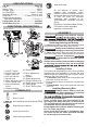
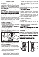
7. Be sure that the collet is not clamped to a fluted
section on the bit shank. The collet should be
clamped to a solid part on the bit shank to ensure
a tight grip.
Minimum
1.6 mm
(1/16")
Bit
shank
Collet nut
Collet
1. Turn the On/Off switch to OFF (O) and remove
the battery pack.
2. Place the trimmer upside down on a workbench.
3. Press and hold the spindle lock and use the 17
mm (11/16") wrench to loosen the collet nut
counterclockwise (or use the 11mm (7/16") spindle
lock wrench to hold the spindle securely).
4. Insert the bit shank into the collet as far as it will
go.
5. Back the bit shank
out slightly to avoid
bottoming out.
6. Be sure there is a
minimum of 1.6 mm
(1/16") between the
bottom of the collet
assembly and the
radius to the cutting
portion of the bit.
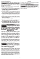
Accessory Plunge Base
1. Open the quick release
2
1
lever. (1)
2.
3.
reverse the procedure.
Insert the tool into the
base. (2)
Close the quick release
lever.
4. To remove the base,