
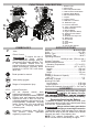
Operator's Manual

5
WARNING
reco
Only use
mmended
accessorie
for thi
s
s tool. Others
may be hazardous.
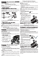
Removing the Vent Plug
Before using the tool, ensure the vent plug is re-
moved.
To remove the vent plug:
3. Push the black collar of the vent up and pull the
red plug out.
NOTE: The plug should be kept to aid in transporting
and servicing the tool (see Transport section).
Vent Plug
Inserting Oil
3. Insert oil, monitoring the level through the oil sight
line.
2.
3.
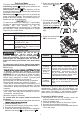
Removing/Replacing the Coupler
WARNING
ers'
Follow the
installation
accessory
instructions.
manufactur
Other
-
uses may cause damage to the tool, accessories,
and workpiece.
To remove the coupler:
1. Remove the battery pack.
4.
Push and hold down the manual release button
Place a wrench on the
coupler swivel to steady
swivel.
5.
WARNING
Only use couplers that are rated
1.
10,000 psi (700 bar) or higher.
To replace the coupler:
2.
Place a second wrench
on the coupler and
loosen coupler.
Remove the battery pack.
swivel.
3. Place a wrench on the coupler swivel to steady
using a second wrench, tighten the coupler into
place.
4. Place the coupler onto the coupler swivel and,
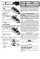
Removing/Attaching the Remote Cord
To remove the remote cord, twist the cord grommet
loose and pull the cord away from the remote or tool.
To attach the remote cord, line up the keys of the
cord to the keys of the remote or tool. Push the cord
into the remote or tool and twist the cord grommet
until tight.
For best performance, always use Hydraulic Oil to
refill the reservoir.
NOTE: The proper oil fill level is half way through
the oil sight line (0.7l). Excess oil will flow out
through the pump vent.
Once removed, clean
out any thread tape still
in the coupler area.
Ensure the new coupler has thread tape. If it does
not, place two wraps of tape on the threads of the
coupler.
NOTE: Only use thread tape.
NOTE: The coupler should be torqued to 61 - 74 Nm.
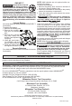
Priming the Hydraulic System
The tool should be primed any time that it has run
dry of oil.
To prime the system:
1. Remove the battery pack.
2. Inspect the oil sight line and ensure the tool has
enough oil.
3. Connect the coupler to an accessory head that
will siphon out the air and excess oil.
NOTE: The coupler must be pointed straight up,
and the tool must be positioned lower than the ac-
cessory head.
4. Insert the battery pack.
5. Press the hold pressure button.
6. Run the tool.
NOTE: It may take up to thirty seconds for air and
oil to start coming out.
2
sec
7. Once the oil starts coming
out, press and hold the
manual release button for
two seconds, then release
both buttons.
8. Repeat steps 5-7 three to
1. Remove the battery pack.
2. Connect the accessory hose to the coupler.
NOTE: The coupler must be pointed to the side, and
the tool must be positioned higher than the accessory
hose and head.
four times.
NOTE: While priming the sys-
tem, make sure the oil level
does not drop below the oil
if necessary.
Bleeding the Accessory
Accessories should be bled of air any time an accessory
has been serviced, unused for a long period of time
Please also consult accessory manufacturer's recom-
mendations for further bleeding instructions.
To bleed an accessory:
2
sec
3. Insert the battery pack.
4. Press the hold pressure button.
5. Run the tool until the cy-
cle completes, and the
pressure indicator lights
green.
6. Press and hold the manual
release button for two sec-
onds, then release both
buttons.
7. Repeat steps 4-6 three to
four times.
NOTE: While bleeding the
accessory, make sure the oil
level does not drop below the
if necessary.