
Operator's Manual


4
Mode RPM IPM Mode RPM IPM
Cat. No. M18 ONEFHIWP12
1 0-950 0-1150 3 0-1800 0-2400
2 0-1500 0-2100 4 0-1800* 0-2400*
Cat. No. M18 ONEFHIWF12
1 0-550 0-950 3 0-1750 0-2100
2 0-1400 0-1750 4 0-1750* 0-2100*
Cat. No. M18 ONEFHIWF34
1 0-950 0-1150 3 0-1800 0-2400
2 0-1500 0-2100 4 0-1800* 0-2400*
* In Mode 4, when run in reverse, the tool will spin
at the above RPM and IPM until the nut breaks free
from the joint. Then, the tool slows to 750 RPM for
better control in removing the nut.
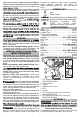
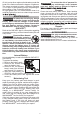
Using the Control Switch
The control switch may be set to three positions:
forward, reverse and lock. Due to a lockout mecha-
nism, the control switch can only be adjusted when
the ON/OFF switch is not pressed. Always allow the
motor to come to a complete stop before using the
control switch.
Push for
Forward
rof hsuP
Reverse
PUSH TO CENTRE TO LOCK
1. For forward (clockwise) rotation, push the control
switch in the direction shown. Check the direction
of rotation before use.
2. For reverse (counterclockwise) rotation, push the
control switch in the direction shown. Check the
direction of rotation before use.
3. To lock the trigger, push the control switch to the
centre position. The trigger will not work when the
control switch is in the locked position.
Always remove the battery pack before performing
maintenance or changing accessories. Always
lock the trigger or remove the battery pack before
storing the tool and any time the tool is not in use.
Starting, Stopping and Controlling Speed
These tools may be operated at any speed from 0
to full speed.
1. To start the tool, pull the trigger.
NOTE: An LED is turned on when the trigger is pulled.
2. To vary the driving speed, increase or decrease
pressure on the trigger. The further the trigger is
pulled, the greater the speed.
3. To stop the tool, release the trigger.
Impacting Techniques
The longer a bolt, screw, or nut is impacted, the
tighter it will become. To help prevent damaging the
fasteners or workpieces, avoid excessive impact-
ing. Be particularly careful when impacting smaller
fasteners because they require less impacting to
reach optimum torque.
Practice with various fasteners, noting the length of
time required to reach the desired torque. Check the
tightness with a hand-torque wrench. If the fasteners
are too tight, reduce the impacting time. If they are
not tight enough, increase the impacting time.
WARNING
Always remove battery pack before
changing or removing accessories.
To insert the battery, slide the pack into the body
of the tool. Make sure it latches securely into place.
WARNING
recommended for this tool. Others
may be hazardous.
-
cally designed for use on impact wrenches and
drivers. Other sockets and accessories might
shatter or break causing injury.
Attaching and Removing Accessories
1/2" Impact Wrench with Pin Detent
(Cat. No. M18 ONEFHIWP12)
1. Use only the appropriate size Square Drive Sockets.
2. To attach a socket, align the hole in the accessory
with the detent pin on the anvil. Hold the detent
pin in while pushing the socket onto the anvil.
The detent pin will snap into place in the hole to
secure the socket.
3. To remove the socket, insert a nail or other thin
object into the hole in the accessory and press
in the detent pin. Pull the accessory off the anvil.
1/2" & 3/4" Impact Wrench
with Friction Ring
(Cat. No. M18 ONEFHIWF12 and M18 ONEFHIWF34)
1. Use only the appropriate size Square Drive Sockets.
2. To attach a socket, align the accessory with the
3. To remove the accessory, pull the accessory off
the anvil.
ONE-KEY™
OPERATION
WARNING
Always remove battery pack before
changing or removing accesso-
-
mended for this tool. Others may be hazardous.
To reduce the risk of injury, wear safety goggles
or glasses with side shields.
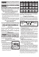
Using the Drive Control
The drive control button is used to adjust the torque,
rotation speed (RPM), and impact speed (IPM) for
the application.
To select the drive control mode:
Drive Control Button
Mode
Indicator
ONE-KEY™
1. Pull and release the trigger
to turn on the tool. The cur-
rent mode indicator is lit.
2. Press the drive control but-
ton
to cycle through the
modes. Select wireless
to change the default set-
tings via the ONE-KEY App
on your smart device. When the desired mode
indicator is lit, begin work.
To learn more about the ONE-KEY™ functionality
for this tool, please reference the Quick Start guide
included with this product or go to
milwaukeetools.com.au/One-Key.
To download the
ONE-KEY app, visit the App Store or Google Play
from your smart device.