
Replacement Parts List

1
(2x)
4
3
2a
5
4
5
6
Or:
End cap push/pull body
End cap
main body
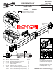
Each End Cap Assembly should come
fully assembled.
Open the push/pull body to allow easy
installation of End Cap Assembly into
frame of level, as shown in fig. 1.
With End Cap Assembly fully seated in
frame, depress the push/pull body to
lock assembly in place, see fig. 2.
fig. 1 fig. 2
Threaded
Screw
3
2b
Snap
Tab
FIG. PART NO. DESCRIPTION OF PART NO. REQ.
1 MLDENDCP Replacement End Cap Kit (Set of 2) (1)
2a 42-92-0102 Replacement Battery Door with Snap Tab (1)
2b 42-92-0104 Replacement Battery Door with Threaded Screw (1)
3 48-11-2130 REDLITHIUM USB Battery Pack (1)
4 --------------- USB Wall Adapter (1)
5 --------------- 36" Micro USB Cable (1)
6 48-59-1202 USB Micro Cable and AC Plug Kit (1)
7 MLDSB14 Soft Case for MLDIG14 Digital Level (Not Shown) (1)
MLDSB24 Soft Case for MLDIG24 Digital Level (Not Shown) (1)
MLDSB48 Soft Case for MLDIG48 Digital Level (Not Shown) (1)
MLDSB72 Soft Case for MLDIG72 Digital Level (Not Shown) (1)
54-49-5212
SERVICE PARTS LIST
BULLETIN NO.
MILWAUKEE TOOL
l
www.milwaukeetool.com
13135 W. LISBON RD., BROOKFIELD, WI 53005
Drwg. 2
EXAMPLE:
Component Parts (Small #) Are Included
When Ordering The Assembly (Large #).
0
00
MLDIG14
MLDIG24
DIGITAL LEVELS
Aug. 2019
REVISED BULLETIN
WIRING INSTRUCTION
DATE
CATALOG NO.
SPECIFY CATALOG NO. AND SERIAL NO. WHEN ORDERING PARTS
Model MLDIG24
Shown
MLDIG48
MLDIG72
NOTE: There are two dierent replacement battery doors
for the models listed above, please visually conrm
which door needs to be ordered.
2a Battery Door with Snap Tab design 42-92-0102
2b Battery Door with Threaded Screw 42-92-0104