
Use and Care Manual


5
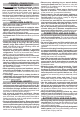
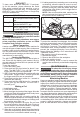
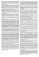
FUNCTIONAL DESCRIPTION
1
2
4
7
9
14
13
12
15
16
17
18
3
8
5
6
11. Water supply valve
12. Quick connect tting
13. ONE-KEY
™ indicator
14. Overheat indicator
15. Spindle bolt
16. Roller wheels
17. Scrench/storage
18. Hex wrench
1. Trigger
2. Rear handle
3. Trigger lock
4. Arm button
5. Battery latch lever
6. Battery latch lock
7. Front handle
8. Water supply tube
9. Wheel guard handle
10. Spindle lock access
hole
10
11
ASSEMBLY
WARNING
Recharge only with the charger
specied for the battery. For spe-
cic charging instructions, read the operator’s
manual supplied with your charger and battery.
Removing/Inserting the Battery
To remove the battery, push the battery latch to the
side and squeeze the battery latch lever. Pull the
battery pack away from the machine.
WARNING
Always remove battery pack before
changing or removing accessories.
To insert the battery, slide the pack into the body of
the machine. Make sure it latches securely into place.
WARNING
Only use accessories specically
recommended for this machine.
Others may be hazardous.
WARNING
To reduce the risk of injury, use a
cut-o wheel which is rated with a
maximum safe operating speed at least 5370 RPM.
READ SAFETY INFORMATION SUPPLIED WITH
CUT-OFF WHEEL. Always wear proper safety
equipment, including a dust mask.
Installing and Removing Cut-O Wheels
1. To install cut-o wheels, remove battery pack.
2. Place machine on a rm surface.
3. Move wheel guard for easier access to spindle bolt.
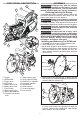
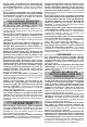
4. Slide the inner ange, arbor adaptor, cut-o wheel,
and outer ange over the spindle. Be sure the
arbor adapter matches the wheel arbor hole size
(20 mm or 1").
Bolt
Outer ange
Inner ange
Spindle
Arbor adapter
Wheel
5. While holding the spindle lock in place with the
hex wrench (1), install and tighten the spindle bolt
securely with the scrench (2).
1
2
6. To remove cut-o wheels, hold the spindle lock
in place and loosen the spindle bolt with the
scrench. Remove the spindle bolt, outer ange,
arbor adapter, and cut-o wheel.