
Operator's Manual


4
SPECIFICATIONS
Cat. No. .............................................. MXF DR150
Vacuum Pump ..................................... 49-50-0200
Gasket Kit ............................................ 43-44-0019
SYMBOLOGY
Read operator's manual
Always wear eye, hearing, and
respirator protection
Regulatory Compliance Mark (RCM).
This product meets applicable
regulatory requirements.
ADDITIONAL BATTERY SAFETY RULES
WARNING
To reduce the risk of fire,
personal injury, and product
damage due to a short circuit, never immerse your
tool, battery pack or charger in fluid or allow a fluid
to flow inside them. Corrosive or conductive fluids,
such as seawater, certain industrial chemicals, and
bleach or bleach-containing products, etc., can
cause a short circuit.
WARNING
Do not charge
non-rechargeable batteries.
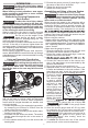
1. Set the base on the ground upright.
2. Align holes in wheel base to the back of the stand,
as shown.
3. Insert the bolt(1) through the holes connecting
the wheel assembly to the base and insert cotter
pin(2) through the hole in the end of the bolt.
4. Tighten the knob screw(3) in back end of wheel
assembly securely.
Mounting the Core Drill to the Stand
WARNING
To reduce the risk of injury, always
unplug drill or remove battery be-
fore installing the drill.
Use a MILWAUKEE® MX FUEL™ Core Drill with
this stand.
1. To mount the drill, loosen the mount plate handle(1).
2. Place core drill, spindle-down, into the mount plate(2).
3. Hand tighten the mount plate handle. If the core
drill prevents the mount plate handle from fully
rotating, pull out the handle, rotate back, push in,
tighten and repeat.
4. After the core drill is mounted, ensure the carrier
is rigid against the mast. A loose carrier can allow
the drill or bit to wobbling during coring. Wiggle
the drill front to back and side to side. If it moves,
tighten the mount plate. If the drill continues to
feel loose, see "Adjusting Carrier Assembly" in
the Maintenance section for more information.
5. To remove drill, loosen the mount plate handle and
pull the drill away from the stand.
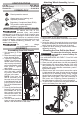
ASSEMBLY
Assembling Core Drill Stands
1. Set the base(1) on the
ground.
Angle
Brace
2. Raise the mast(2) upright
to the desired angle.
3. Tighten the angle brace
handle(3) securely. If
handle cannot turn fully
due to setup orientation,
pull out the handle, rotate
back, push in, tighten
and repeat.
4. Slide carrier assembly(4)
onto the mast, match-
ing carrier wheels with
grooves in the mast.
NOTE: Over time, the
carrier assembly may
become loose and need
to be tightened (see "Ad-
justing Carrier Assem-
bly" in the Maintenance
section)
5. Press in the feed handle
button(5) and insert the
feed handle into one of
the handle locations.
Release the button. En-
sure the handle clicks
into place.
6. Turn the feed handle to
lower or raise the carrier. When the carrier is fully
raised, it can be lifted off of the mast.
Attaching Wheel Assembly (Optional)
1
1
2
3
3
2
1
2
4
5
2