
Product Manual


page 9
Step 2 - Adjusting the Guide Tubes
If the saw does not cut at 90°, the guide tubes may not be perpendicular
to the rollers. Unplug the saw cord before testing alignment or making
adjustments. Check the alignment of the rollers before adjusting the
guide tubes (see "Adjusting the Rollers").
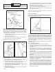
1. To check the guide tube alignment, remove the upper guard assem-
bly to expose the blade. Mark a tooth to use as a reference. If using
a high-speed steel blade, mark a tooth pointing toward the edge of
the field alignment tool.
2. Clamp the field alignment tool to the roller assembly and pull the saw
carriage down slowly so the marked reference tooth just touches
the vertical edge of the field alignment tool. Continue to pull the saw
carriage down. If the blade does not contact the square, or if the
blade binds on the square, the guide tubes are not aligned.
3. To align the guide tubes, determine which direction the top of the
guide should move. If the blade runs into the square, the top guide
goes to the square. If the blade runs away from the square, the top
guide goes away from the square.
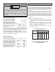
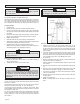
Fig. 12
Guide tube
bracket nuts
4. Loosen the guide tube bracket nuts (Fig. 12), but do not remove the
tube bracket.
NOTE: Figure 12 shows the counterbalance removed for illustration
purposes. It is not necessary to remove the counterbalance to per-
form this procedure.
5. Using a deadblow mallet, strike the bracket on the side and in the
direction the tubes need to move.
6. Recheck the squareness of the tubes to the rollers repeating the
procedure as necessary.
7. Tighten the nuts on the upper guide tube bracket nuts.
Step 3 - Adjusting the Blade - Parallelism
The blade should be parallel to the guide tubes, otherwise tail burning
may occur and the kerf will be wider than the set of the blade. Make the
following adjustments only if the blade appears to be out of alignment.
ALWAYS check for alignment of the rollers and the guide tubes before
adjusting the blade.
1. To check for blade parallelism, position the saw carriage for a cross-
cut and make a sample cut. If the blade "heels", burns marks on the
cut, etc., check both sides of the cut to determine which side of the
blade is causing the problem.
2. Unplug the tool.
3. Position the square on the rollers and lower the saw carriage so the
square overhangs the blade.
4. Place the square against the blade. The entire face of the blade
should contact the square. If it does not, then the blade is not parallel
to the workpiece.
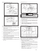
Factory-set
adjustment
screw
5. Loosen (but do not remove) the two hex head nuts holding the index
pin bracket (Fig. 13). If burn marks appear on the left side of the
workpiece, rotate the saw slightly clockwise until the entire face of
the blade contacts the square. If burn marks appear on the right side
of the workpiece, rotate the saw slightly counterclockwise until the
entire face of the blade contacts the square. ONLY make slight
adjustments.
6. Securely tighten the two hex head nuts holding the index pin bracket.
7. Plug in the tool and make another sample cut. Repeat the procedure
if necessary.
Step 4 - Adjusting the Blade - Perpendicularity
If you remove the saw motor without making sure that the factory-set
adjustment screw contacts the plate on the saw motor, then the blade
will not be perpendicular (90°) to the workpiece, possibly resulting in
inaccurate cuts.
1. Unplug the tool.
2. To adjust for perpendicularity, loosen the two mounting nuts on the
front of the saw motor. The adjustment screw is located to the right
of these nuts (Fig. 13).
3. Loosen the lock nut under the bracket. Tighten or loosen the adjust-
ment screw depending on the angle adjustment required. ONLY
make slight adjustments.
4. Tighten the lock nut, making sure the screw is against the upright
plate.
5. Tighten the two hex nuts to secure the saw.
6. Plug in the tool and make a sample cut. Repeat the procedure if
necessary.
Mounting nut
Fig. 13
Index Pin
Bracket
Mounting nut