Portable Generator Operator’s Manual This generator is rated in accordance with CSA (Canadian Standards Association) standard C22.2 No. 100-04 (motors and generators) and PGMA (Portable Generator Manufacturers’ Association) standard PGMA G200 (Standard for Testing and Validating Performance of Portable Generators). BRIGGS & STRATTON POWER PRODUCTS GROUP, LLC MILWAUKEE, WISCONSIN, U.S.A. Manual No.
Thank you for purchasing this quality-built Troy-Bilt generator. We are pleased that you’ve placed your confidence in the Troy-Bilt brand. When operated and maintained according to the instructions in this manual, your Troy-Bilt generator will provide many years of dependable service. This manual contains safety information to make you aware of the hazards and risks associated with generators and how to avoid them.
Table of Contents Operator Safety . . . . . . . . . . . . . . . . . . . . . . . . . . . . . . . . . 4 Equipment Description. . . . . . . . . . . . . . . . . . . . . . . . . . . . . . . . . . . . . . . . . 4 Important Safety Information. . . . . . . . . . . . . . . . . . . . . . . . . . . . . . . . . . . . 4 Assembly . . . . . . . . . . . . . . . . . . . . . . . . . . . . . . . . . . . . . 7 Unpack Generator . . . . . . . . . . . . . . . . . . . . . . . . . . . . . . . . . . . . . . . . . . . .
Operator Safety Equipment Description Read this manual carefully and become familiar with your generator. Know its applications, its limitations and any hazards involved. The generator is an engine–driven, revolving field, alternating current (AC) generator. It was designed to supply electrical power for operating compatible electrical lighting, appliances, tools and motor loads. The generator’s revolving field is driven at about 3,600 rpm by a single-cylinder engine.
WARNING Starter cord kickback (rapid retraction) will pull hand and arm toward engine faster than you can let go which could cause broken bones, fractures, bruises, or sprains resulting in serious injury. • When starting engine, pull cord slowly until resistance is felt and then pull rapidly to avoid kickback. • NEVER start or stop engine with electrical devices plugged in and turned on.
WARNING Generator voltage could cause electrical shock or burn resulting in death or serious injury. • Use approved transfer equipment to prevent backfeed by isolating generator from electric utility workers. • When using generator for backup power, notify utility company. • Use a ground fault circuit interrupter (GFCI) in any damp or highly conductive area, such as metal decking or steel work. • DO NOT touch bare wires or receptacles.
Assembly Read entire operator’s manual before you attempt to assemble or operate your new generator. Your generator requires some assembly and is ready for use after it has been properly serviced with the recommended fuel and oil level is verified. If you have any problems with the assembly of your generator, please call the generator helpline at (888) 611-6708. If calling for assistance, please have the model, revision, and serial number from the identification label available.
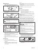
Moving Generator 1. Remove handle pin (A) from bracket on right side of handle (viewing generator from engine end). A NOTICE Improper treatment of generator could damage it and shorten its life. • DO NOT attempt to crank or start the engine before it has been properly serviced with the recommended oil. This may result in an engine failure. 4. Replace oil fill cap/dipstick and fully tighten. Add Fuel 2. Pull folding handle to the upright position until latch (B) locks into place.
High Altitude At altitudes over 5,000 feet (1524 meters), a minimum 85 octane / 85 AKI (89 RON) gasoline is acceptable. To remain emissions compliant, high altitude adjustment is required. Operation without this adjustment will cause decreased performance, increased fuel consumption, and increased emissions. See an authorized dealer for high altitude adjustment information. Operation of the engine at altitudes below 2,500 feet (762 meters) with the high altitude kit is not recommended.
System Ground The generator has a system ground that connects the generator frame components to the ground terminals on the AC output receptacles. The system ground is connected to the AC neutral wire (the neutral is bonded to the generator frame). Generator Location Carbon Monoxide Poisoning Special Requirements There may be Federal or State Occupational Safety and Health Administration (OSHA) regulations, local codes, or ordinances that apply to the intended use of the generator.
Features and Controls Generator Read this Operator’s Manual and safety rules before operating your generator. Compare the illustrations with your generator, to familiarize yourself with the locations of various controls and adjustments. Save this manual for future reference. N A B C M D E F L G K H J A - Main Control Panel — Permanently affixed to generator. See Control Panel on next page. B - Extend-a-panel™ — May be removed and connected to generator with accessory cord for remote operation.
Control Panel Read this Operator’s Manual and safety rules before operating your generator. Compare the illustrations with your control panel, to familiarize yourself with the locations of various controls and adjustments. Save this manual for future reference. A B K C D E J F G A - 120 Volt AC, 20 Amp, GFCI Duplex Receptacles — May be used to supply electrical power for the operation of 120 Volt AC, 20 Amp, single phase, 60 Hz electrical, lighting, appliance, tool and motor loads.
Battery Charger Use battery float charger jack to keep the starting battery charged and ready for use. Battery charging should be done in a dry location, such as inside a garage. 1. Plug charger into unit’s “Battery Float Charger” jack, which is located above on/off switch. Plug battery charger into a 120 Volt AC wall receptacle. A double pole rocker switch circuit breaker is provided to protect the locking receptacle. If this circuit breaker is tripped, all receptacles are disconnected.
Extend-a-panel™ A double pole rocker switch circuit breaker on the main panel is provided to protect the cordset off main panel. If this circuit breaker is tripped, all power from cordset is disconnected. 120 Volt AC, 20 Amp, GFCI Duplex Receptacles The Extend-a-panel™ has two 120 Volt, 20 Amp GFCI duplex receptacles. Each receptacle is protected against overload by push-to-reset circuit breakers. Testing the GFCI Test your GFCI outlet prior to each use, as follows: • Push the “Test” button.
Extend-a-panel™ LCD The Extend-a-panel™ also has a built in LCD display with alarm system to monitor the following features: • Dual Load Monitor (Panel and Total) • Maintenance Reminder • Security Warning • Generator Shutdown Dual Load Monitor The dual load monitor measures the wattage output of the Extend-a-panel™ 120V, 20A receptacles and will display “PANEL” along with bars and percentage of load.
Operation 5B. For manual starting, grasp recoil handle and pull slowly until slight resistance is felt. Then pull rapidly one time only to start engine. Starting the Engine NOTICE Always unplug the battery float charger before starting the generator. Disconnect all electrical loads from the generator. Use the following start instructions: 1. Make sure unit is on a level surface. NOTICE Failure to start and operate the unit on a level surface will cause the unit not to start or shut down during operation.
Connecting Electrical Loads Stopping the Engine 1. Let engine stabilize and warm up for a few minutes after starting. 2. Ensure rocker switch circuit breakers on main panel are in “On” position. 3. Plug in and turn on the desired 120 and/or 240 Volt AC, single phase, 60 Hz electrical loads. NOTICE When plugging into the 120 Volt receptacles on Extend-a-panel™, plug items to be powered in sequence as shown below. 1. Turn OFF and unplug all electrical loads from generator panel receptacles.
Creating a Temporary Cold Weather Shelter 1. For temporary shelter, the original shipping carton can be used. 2. Cut off top carton flaps and one long side of carton to expose muffler side of unit. If required, tape up other sides of carton to fit over generator as shown. Wind 6. Start generator as described in the section Starting the Engine, then place carton over generator. Keep at least 5 ft. (1.5 m) clearance on all sides of generator including overhead with shelter in place.
Don’t Overload Generator Capacity You must make sure your generator can supply enough rated (running) and surge (starting) watts for the items you will power at the same time. Follow these simple steps: 1. Select the items you will power at the same time. 2. Total the rated (running) watts of these items. This is the amount of power your generator must produce to keep your items running. See Wattage Reference Guide. 3. Estimate how many surge (starting) watts you will need.
Maintenance Maintenance Schedule Follow the hourly or calendar intervals, whichever occurs first. More frequent service is required when operating in adverse conditions noted below.
Fuel Valve Maintenance The fuel valve is equipped with a fuel sediment cup, screen, and o-ring that need to be cleaned. 1. Move fuel valve to “Off” position. 2. Remove sediment cup (A) from fuel valve. Remove o-ring (B) and screen (C) from fuel valve. C * Below 40°F (4°C) the use of SAE 30 will result in hard starting. ** Above 80°F (27°C) the use of 10W30 may cause increased oil consumption. Check oil level more frequently. B A 3. Wash sediment cup, o-ring, and screen in a nonflammable solvent.
Changing Engine Oil If you are using your generator under extremely dirty or dusty conditions, or in extremely hot weather, change the oil more often. CAUTION Avoid prolonged or repeated skin contact with used motor oil. • Used motor oil has been shown to cause skin cancer in certain laboratory animals. • Thoroughly wash exposed areas with soap and water. KEEP OUT OF REACH OF CHILDREN. DON’T POLLUTE. CONSERVE RESOURCES. RETURN USED OIL TO COLLECTION CENTERS.
Inspect Muffler and Spark Arrester The engine exhaust muffler has a spark arrester screen. Inspect the muffler for cracks, corrosion, or other damage. Remove the spark arrester and inspect for damage or carbon blockage. If replacement parts are required, make sure to use only original equipment replacement parts. WARNING Exhaust heat/gases could ignite combustibles, structures or damage fuel tank causing a fire, resulting in death or serious injury.
Storage The generator should be started at least once every seven days and allowed to run at least 30 minutes. If this cannot be done and you must store the unit for more than 30 days, use the following guidelines to prepare it for storage. Generator Storage • Clean the generator as outlined in Cleaning. • Check that cooling air slots and openings on generator are open and unobstructed. NOTICE Store Extend-a-panel™ and accessory cord indoors only.
Troubleshooting Problem Engine is running, but no AC output is available. Engine runs well at no-load but "bogs down" when loads are connected. Cause 1. 2. 3. 4. One of the circuit breakers is open. Fault in generator. Poor connection or defective cord set. Connected device is bad. 1. 2. 3. 4. Reset circuit breaker. Contact authorized service facility. Check and repair. Connect another device that is in good condition. 1. 2. 3. 4. Short circuit in a connected load. Engine speed is too slow.
Warranties California, U.S. EPA, and Briggs & Stratton Corporation Emissions Control Warranty Statement Your Warranty Rights And Obligations The California Air Resources Board, U.S. EPA, and Briggs & Stratton (B&S) are pleased to explain the emissions control system warranty on your Model Year 2012-2013 engine/equipment. In California, new small off-road engines and large spark ignited engines less than or equal to 1.
The warranty on emissions-related parts is as follows: • Any warranted part that is not scheduled for replacement as required maintenance in the owner’s manual supplied, is warranted for the warranty period stated above. If any such part fails during the period of warranty coverage, the part will be repaired or replaced by B&S at no charge to the owner. Any such part repaired or replaced under the warranty will be warranted for the remaining warranty period.
TROY-BILT® PORTABLE GENERATOR OWNER WARRANTY POLICY Effective November 1, 2012; replaces all undated Warranties and all Warranties dated before November 1, 2012. LIMITED WARRANTY Troy-Bilt® is a registered trademark of MTD Products Inc. and is used under license to Briggs & Stratton Power Products. Briggs & Stratton Power Products Group, LLC will repair or replace, free of charge, any part(s) of the portable generator that is defective in material or workmanship or both.
Reserved 29
Portable Generator Product Specifications Starting Wattage . . . . . . . . . . . . . . . . . . . . . . .10,500 Watts Wattage* . . . . . . . . . . . . . . . . . . . . . . . . . . . . . .7,000 Watts AC Voltage . . . . . . . . . . . . . . . . . . . . . . . . . . .120/240 Volts at 240 Volts . . . . . . . . . . . . . . . . . . . . . . . . . . .29.1 Amps at 120 Volts . . . . . . . . . . . . . . . . . . . . . . . . . . .58.3 Amps Frequency . . . . . . . . . . . . . . . . . . . . . . . .60 Hz at 3600 rpm Phase . .
Generador portátil Manual del Operario Este generador está clasificado conforme a la norma C22.2 N.º 100-04 (motores y generadores) de la Asociación Canadiense de Normas (Canadian Standards Association, CSA) y la norma PGMA G200 (norma para la evaluación y validación del rendimiento de los generadores portátiles) de la Asociación de Fabricantes de Generadores Portátiles (Portable Generator Manufacturers’ Association, PGMA). BRIGGS & STRATTON POWER PRODUCTS GROUP, LLC MILWAUKEE, WISCONSIN, U.S.A.
Muchas gracias por comprar este generador Troy-Bilt de gran calidad. Nos alegra que haya depositado su confianza en la marca Troy-Bilt. Siempre que sea utilizado de acuerdo con las instrucciones de este manual, su generador Troy-Bilt le proporcionará muchos años de buen funcionamiento. Este manual contiene información sobre seguridad para hacerle consciente de los riesgos asociados a los generadores y mostrarle cómo evitarlos.
Tabla de Contenido Seguridad de operario . . . . . . . . . . . . . . . . . . . . . . . . . . . . 4 Descripción del equipo . . . . . . . . . . . . . . . . . . . . . . . . . . . . . . . . . . . . . . . . 4 Información importante de seguridad . . . . . . . . . . . . . . . . . . . . . . . . . . . . . 4 Montaje . . . . . . . . . . . . . . . . . . . . . . . . . . . . . . . . . . . . . . 7 Desembalaje del generador . . . . . . . . . . . . . . . . . . . . . . . . . . . . . . . . . . . . .
Seguridad de operario Símbolos sobre la seguridad y significados Descripción del equipo Lea atentamente este manual y familiarícese con el generador. Conozca sus aplicaciones, limitaciones y riesgos. Este generador funciona en base a un motor de campo eléctrico giratorio y de corriente alterna (CA). Fue diseñado con la finalidad de proveer energía eléctrica para lámparas eléctricas, aparatos, herramientas y cargas de motor compatibles. El campo giratorio del generador se mueve a unas 3.
ADVERTENCIA El combustible y sus vapores son extremadamente inflamables y explosivos, lo que podría provocar quemaduras, incendios o explosiones; así como lesiones graves o incluso la muerte. ADVERTENCIA PELIGRO DE GAS VENENOSO. Los gases del escape del motor contienen monóxido de carbono, un gas venenoso que podría matarlo en minutos. NO tiene olor, color ni sabor. Aun si no puede oler los vapores del escape, podría estar expuesto al gas de monóxido de carbono.
ADVERTENCIA Los gases y el calor de escape podrían inflamar los materiales combustibles y las estructuras o dañar el depósito de combustible y provocar incendios, así como lesiones graves o incluso la muerte. El contacto con la zona del silenciador podría producir quemaduras y lesiones graves. • NO toque las superficies calientes y EVITE los gases del escape a alta temperatura. • Permita que el equipo se enfríe antes de tocarlo. • Deje un espacio mínimo de 1.
Montaje Su generador requiere de ciertos procedimientos de montaje y solo estará listo para ser utilizado después de haberle suministrado servicio con el combustible y aceite recomendados. Si usted tiene problemas con el montaje de su generador, por favor llame a la línea de ayuda para generadores al (888) 611-6708. Si llamar para la ayuda, tiene por favor el modelo, la revisión y el número de serie de etiqueta de identificación disponible. Consulte la ubicación en la sección Controles y características.
2. Tire del asa de plegado para colocarla en posición vertical hasta que el pestillo (A) quede bloqueado en su posición. Agregue combustible El combustible debe reunir los siguientes requisitos: • Gasolina sin plomo limpia y nueva. • Un mínimo de 87 octanos/87 AKI (91 RON). Para uso a gran altitud, consulte Gran altitud. • Se puede usar gasolina con un contenido de hasta 10% de etanol (gasohol). A 3. Reinserte el pasador del asa en el soporte en el lado derecho de asa.
3. Instale la tapa del tanque de combustible y la espera para algún combustible rociado para evaporar. Gran altitud En altitudes superiores a 1.524 metros (5.000 pies), se deberá utilizar gasolina con un mínimo de 85 octanos / 85 AKI (89 RON). Para seguir cumpliendo la normativa sobre emisiones, es necesario ajustar la unidad para su uso a gran altitud. De no realizarse este ajuste, el rendimiento se reducirá y el consumo de combustible y las emisiones aumentarán.
Tierra del sistema El generador dispone de una conexión a tierra del sistema que conecta los componentes del bastidor a los terminales de tierra de los enchufes hembra de salida de CA. La tierra del sistema está conectada al cable de CA neutro que, a su vez, está conectado al bastidor del generador.
Controles y características Generador Lea este manual del operario y reglas de seguridad antes de poner en marcha su generador. Compare las ilustraciones con su generador, para familiarizarse con la ubicación de los diversos controles y ajustes. Guarde este manual para futuras consultas. N A B C M D E F L G K H J A - Panel de control principal — Siempre está anclado al generador. Consulte Panel de control en la siguiente página.
Panel de control Lea este manual del operario y reglas de seguridad antes de poner en marcha su generador. Compare las ilustraciones con su panel de control, para familiarizarse con la ubicación de los diversos controles y ajustes. Guarde este manual para futuras consultas.
Cargador de batería Utilice el enchufe hembra del cargador de flotación (carga lenta y continua) de la batería para mantener la batería de arranque cargada y preparada para el uso. La carga de la batería se debe realizar en un lugar seco, como el interior de un garaje. 1. Conecte el cargador al conector hembra “Battery Float Charger” (cargador de flotación de la batería) que se encuentra arriba del interruptor on/off. Enchufe el cargador de la batería a una toma de pared de 120 V CA.
Extend-a-panel™ La unidad incluye un disyuntor basculante bipolar en el panel principal para proteger el juego de cables del panel principal. Si este disyuntor se dispara, se desconecta toda la alimentación del juego de cables. Tomas GFCI dobles de 120 V CA y 20 A El Extend-a-panel™ tiene dos tomas GFCI dobles de 120 V y 20 A. Cada toma está protegida contra sobrecargas por medio de disyuntores de rearme por presión.
Cable auxiliar del Extend-a-panel™ El Extend-a-panel™ se puede conectar directamente al generador o se puede usar el cable auxiliar de 20 A de 7,6 m (25 pies). Cuando utilice el cable auxiliar de 7,6 m (25 pies) con el Extend-a-panel™, siempre asegúrese de seguir todas las instrucciones e indicaciones de seguridad del cable. 1. Desenchufe el conector de seguro giratorio del Extenda-panel™ del cable pequeño del conector de seguro giratorio que se encuentra debajo del panel principal del generador. 2.
Función de aviso de mantenimiento El Extend-a-panel™ también incluye una función de aviso de mantenimiento integrada para avisarle cuando es necesario comprobar el aceite, cambiar el filtro de aire, cambiar el aceite y cambiar la bujía. El LED mostrará las siguientes pantallas para los distintos intervalos de mantenimiento: • “CHECK OIL 8HRS HOLD TO RESET” (COMPROBAR ACEITE 8HRS. MANTENER PULSADO PARA REINICIALIZAR) después de cada 8 horas de funcionamiento.
Operando Encienda el motor AVISO Desenchufe siempre el cargador de flotación de la batería antes de arrancar el generador. Desconecte todas las cargas eléctricas del generador. Use las siguientes instrucciones para encender: 1. Asegúrese de que la unidad está en una superficie plana. AVISO Si la unidad no se arranca y utiliza en una superficie plana, se pueden producir problemas de arranque y de parada durante el funcionamiento. 2. Gire la válvula del combustible (A) a la posición "On". A 3.
Conexión de cargas eléctricas 1. Deje que el motor se estabilice y se caliente por dos minutos después del arranque. 2. Asegúrese de que los disyuntores basculantes del panel principal estén en la posición “On”. 3. Enchúfelo y encienda la carga eléctrica deseada (120 y/o 240 V CA, monofásico, 60 Hz.) AVISO Si conecta aparatos a las tomas de 120 V del Extend-a-panel™, hágalo en la secuencia que se muestra a continuación. 1 3 2 4 AVISO • NO conectar cargas de 240 V en las tomas eléctricas dobles.
Creación de una estructura de protección provisional para climas fríos 1. Para estructura de protección provisional, utilice la caja de cartón de embalaje original. 2. Corte las tapas superiores y uno de los laterales largos de la caja de cartón para dejar al descubierto el lado del silenciador de la unidad. Si es necesario, sujete con cinta adhesiva los otros laterales de la caja de forma que queden sobre el generador, como se muestra. viento 6.
No sobrecargar el generador Capacidad Debe asegurarse de que su generador puede proveer los suficientes vatios de potencia continua (vatiaje nominal) y vatios de salida para los elementos que desee alimentar al mismo tiempo. Siga estos sencillos pasos: 1. Seleccione los elementos que quiere alimentar al mismo tiempo. 2. Sume la potencia nominal de esos elementos. Esa es la cantidad de energía que su generador debe producir para mantener sus elementos en funcionamiento. Vea Guía de Referencia de Potencia. 3.
Mantenimiento Plan de mantenimiento Siga los intervalos de horas o de calendario, los que sucedan antes. Si opera en condiciones adversas (señaladas más abajo) es necesario un mantenimiento más frecuente.
Mantenimiento de la batería Aceite La batería inicial no requiere ningún mantenimiento a excepción de la carga de flotación, que se describe en otro apartado. Mantenga la batería y los terminales limpios y secos. AVISO La carga de la batería se debe realizar en un lugar seco, como el interior de un garaje. Recomendaciones sobre el aceite Para obtener el mejor rendimiento, recomendamos utilizar aceites certificados con garantía Briggs & Stratton.
AVISO El llenado de aceite en exceso podría impedir el arranque del motor o provocar dificultades de arranque. • NO llene en exceso. • Si el nivel de aceite está por encima de la marca FULL (LLENO) de la varilla, vacíe aceite para reducir el nivel hasta la marca FULL (LLENO) de la varilla. 4. Instale el varilla de medición, apriete firmemente.
Inspeccione el silenciador y la pantalla apagachispas Inspeccione que el silenciador no presente fisuras, corrosión u otros daños. Desmonte la pantalla apagachispas, si cuenta con una, y verifique que no presente daños ni obstrucción por carbón. En caso de que se necesiten piezas de recambio, asegúrese de usar solamente piezas de recambio originales para el equipo.
Almacenamiento El generador deberá ser encendido al menos una vez cada siete días y deberá dejarlo funcionar al menos durante 30 minutos. Si no puede hacer esto y debe almacenar la unidad por más de 30 días, siga las siguientes instrucciones para preparar su unidad para almacenamiento. Generador 1. Limpie el generador como está descrito en Limpieza en la sección Mantenimiento. 2. Revise que las ranuras para el aire de enfriamiento y las aperturas del generador se encuentren abiertas y despejadas.
Resolución de problemas Problemo Causa Accion 1. Reposicione el interruptor. El motor está funcionando pero no existe salida de AC disponsible. 1. El interruptor de circuito está abierto. 2. Conexión mal o defectuosa del juego de cables. 3. El dispositivo conectado está dañado. 4. Avería en el generador. El motor funciona bien sin carga pero "funciona mal" cuando se le contectan cargas. 1. Corto circuito en una de las cargas conectadas. 2. El generador está sobrecarga. 3.
Garantías Garantía de control de emisiones de California, U.S. EPA y Briggs & Stratton Corporation Derechos y obligaciones de la garantía California Air Resources Board, U.S. EPA y Briggs & Stratton (B&S) le explican a continuación la garantía del sistema de control de emisiones de su motor/equipo modelo 2012-2013.
La garantía de los componentes relacionados con las emisiones es la siguiente: • Los fallos de todo componente cubierto por la garantía que no se deba sustituir como parte del plan de mantenimiento obligatorio detallado en el manual del propietario entregado quedarán cubiertos por la garantía durante el período de la garantía especificado anteriormente.
POLÍTICA PARA EL PROPIETARIO DE GENERADOR PORTÁTIL TROY-BILT® Fecha de entrada en vigor: 1 de noviembre de 2012; sustituye a todas las garantías sin fecha y a las de fecha anterior al 1 de noviembre de 2012. GARANTÍA LIMITADA Troy-Bilt® es una marca registrada de MTD Products Inc. bajo licencia de Briggs & Stratton Power Products.
Generador portátil Especificaciones del producto Vataje que Empieza . . . . . . . . . . . . . . . . . . . . .10,500 Vatios Vataje* . . . . . . . . . . . . . . . . . . . . . . . . . . . . . . .7,000 Vatios Corriente valorada de Carga de C.A.: a 240 Voltios . . . . . . . . . . . . . . . . . . . . . . .29.1 Amperios a 120 Voltios . . . . . . . . . . . . . . . . . . . . . . .58.3 Amperios Frecuencia Nominal . . . . . . . . . . . . . . . . .60 Hz at 3600 rpm Fase . . . . . . . . . . . . . . . . . . . . . . . . .