
Specifications


Table Of Contents
- TABLE OF CONTENTS
- CAUTION
- Foreword
- For safe operation
- How to Read This Operation Manual
- CHAPTER 1 Before Use
- CHAPTER 2 Basic Operations
- CHAPTER 3 Useful Function
- Changing origin
- Adjusting head gap
- When nozzles missing can not be improved
- Setting the print condition in a set
- Setting the print condition
- Setting media compensation
- Setting the print method
- Registering head gap value
- Set the scan width of the head
- Changing the UV illumination intensity
- Sets UV irradiation at starting/ ending of drawing
- Setting the priority
- Sets the cooling time per scan
- Initializing the settings
- Turning OFF the UV lamp
- Setting the UV lamp OFF duration
- Changing the UV illumination intensity
- MACHINE SETUP
- Other useful functions
- CHAPTER 4 How to care
- Maintaining
- Ink cartridge
- Washing cartridge
- Cleaning the flushing box
- Avoiding ink dripping at printing
- When the waste ink tray is full
- Setting nozzle face cleaning time
- Perform cleaning automatically when the power supply is turned on
- Preventing nozzle dropout while power-off
- Regular maintenance of white ink
- If blur or missing remains
- Wiper cleaning
- Refill antifreeze liquid
- Cleaning of the UV lamp filter
- Cleaning of the UV power supply filter
- Cleaning of the optional vacuum unit filter
- Replacing the mist fan filter
- Replacing UV lamp
- Checking method of UV illumination intensity
- Cleaning of the Ionizer
- Prevent the nozzle clogging of spot color
- CHAPTER 5 In Case of Trouble
- CHAPTER 6 Appendix
4-41
Checking method of UV illumination intensity
4
How to care
Check the UV illumination intensity
1
Turn ON the power supply. ( P.2-4)
2
When <LOCAL> is displayed, press the
key.
3
Select [LEVEL CHECK] with the
key, and press the key.
4
Press the key.
• The carriage will move automatically from the
waiting position (left side) to the right side.
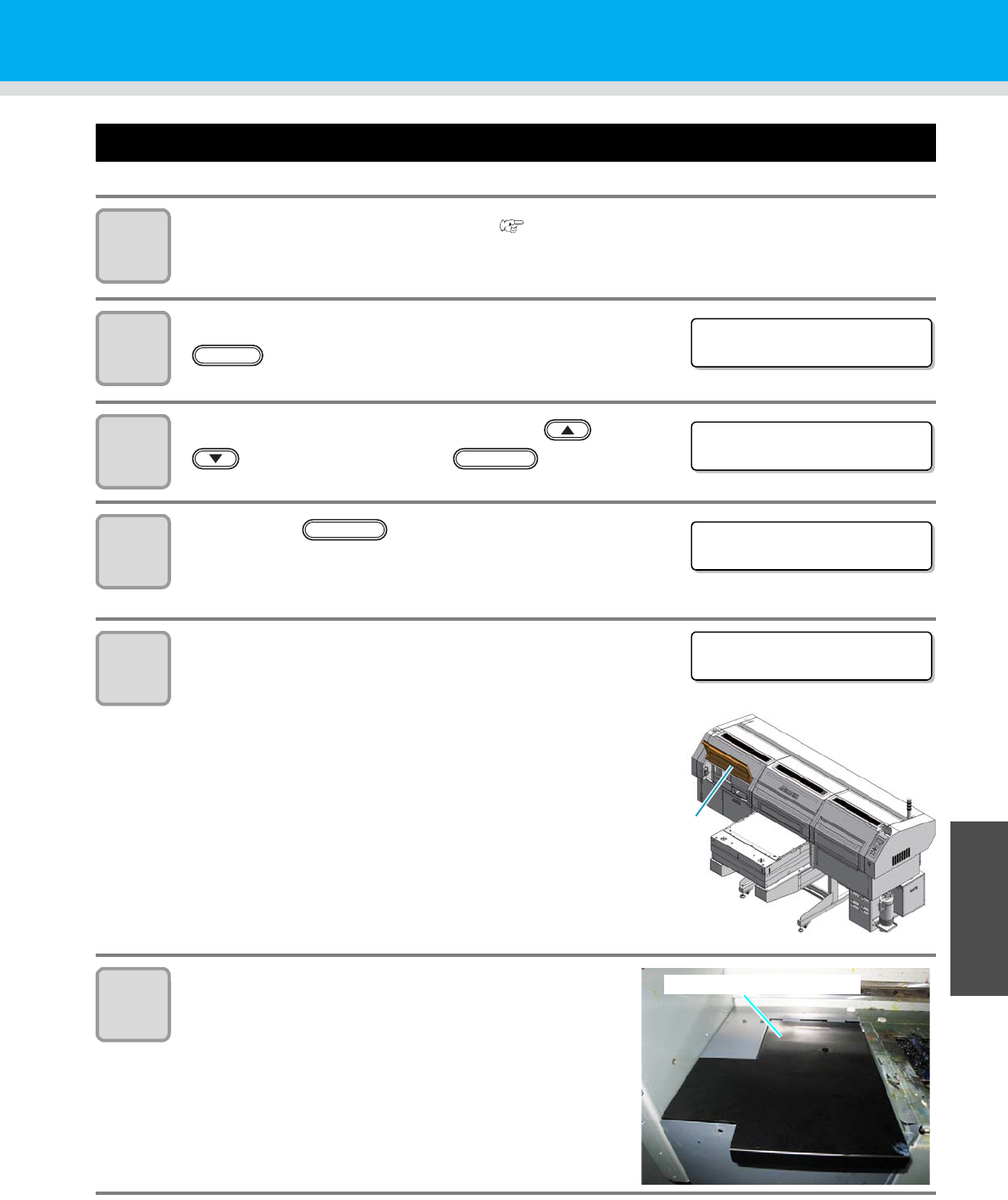
5
Remove the screws (on two places)
and the front left cover.
6
Remove the illumination meter bracket
and insert the sensor part into the
square hole on the rear surface.
<LOCAL . 1>
UV
UV LAMP
LEVEL CHECK < e n t >
ENTER
UV LEVEL CHECK
HEAD MOVE : e n t
ENTER
PLEASE OPEN
THE LEFT COVER
Front left
cover
Illumination meter bracket