Quick Start Set the front panel switches to the following positions: On/Off Hold for FP Search Mode Soil / Timings Ground Balance Coil / Rx Patch Sensitive Fixed Double D G N Deep Salt M Tracking Cancel Threshold Press the On/Off button on the rear control panel. (pg. 25) Turn the Threshold control up until a tone is audible through the headphones. (pg. 34) Raise the coil off the ground and Press the Auto Tune button to reduce electrical interference.
Minelab is always interested in your opinions. If you have any questions or comments regarding the GPX-4000 or any other Minelab product, please feel free to contact us via your local Authorised Minelab dealer, or write to us: Minelab Electronics Pty Ltd PO Box 537, Torrensville Plaza Adelaide, South Australia, 5031 Australia Tel: +61 (0) 8 8238 0888 Fax: +61 (0) 8 8238 0890 Email: minelab@minelab.com.
Congratulations on Purchasing the Minelab GPX-4000 1 Gold detecting is a fascinating and rewarding activity enjoyed by people all over the world. By getting to know your GPX-4000 you can become one of the many who find gold and valuable treasure. The GPX-4000 is Minelab's most advanced gold detector. It is a high precision instrument incorporating Multi-Period Sensing (MPS), Dual Voltage Technology (DVT), and the latest in high-tech analogue components combined with advanced digital processing.
2 Contents 3 Quick Start Introducing the GPX-4000 List of Parts Assembly Adjusting the Detector for Comfortable Detecting Charging the Battery Battery LED Patterns Taking Care of Your Battery Auto Tune Threshold Search Mode Soil / Timings Ground Balance Coil / Rx Patch Sensitive Fixed Double D G N Deep Salt M Tracking Cancel Coil Smart Point Back Cover 4 6 8 16 18 20 21 Detecting Basics Detector Sounds Front Control Panel Rear Control Panel Turning the Detector On LCD Menu Structure Se
4 Introducing the GPX-4000 5 The GPX-4000 utilises Minelab’s proven 'Dual Voltage Technology' (DVT). This ensures an accurate Ground Balance to provide maximum sensitivity and depth in all ground types. The GPX-4000 can handle heavily mineralised and salty ground conditions with greater ease than previous detectors, which effectively opens up NEW detecting areas.
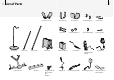
List of Parts 7 "SNSFTU TFDUJPOT "SNSFTU 4USBQT "SNSFTU $PWFS 7FMDSP 5BCT %% $PJM -PXFS 4IBGU #BUUFSZ )BSOFTT 6QQFS 4IBGU 8BJTUCFMU $POUSPM #PY #VOHZ $PSE $MBNQ #PX ,OVDLMF #PMU 8JOHOVU -JUIJVN *PO #BUUFSZ #VOHZ $PSE "SNSFTU 8JOHOVUT "SNSFTU #PMUT -PXFS 4IBGU 8BTIFST -PXFS 4IBGU 8JOHOVU -PXFS 4IBGU #PMU 1PXFS $BCMF )BOEMF XJUI 2VJDL 5SBL #VUUPO )FBEQIPOFT 7FIJDMF $IBSHFS "EBQUPS .BJOT $IBSHFS "EBQUPS *OTUSVDUJPO .
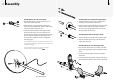
8 Assembly 9 Attaching the Coil to the Lower Shaft: Attaching the Lower Shaft to the Upper Shaft: 1 Plug the two rubber washers into the holes on either side of the lower shaft. 1 Rotate the twistlock of the upper shaft counterclockwise to ensure that it is loosened. 2 Ensure that the spring loaded pin of the lower shaft is pointing downwards. Slide the lower shaft into the bracket on top of the coil. 2 Compress the spring loaded pin of the lower shaft.
10 Assembly 11 Attaching the Armrest Strap to the Armrest: Always ensure that the control box is turned off before connecting or disconnecting the coil to avoid damage to the detector's electronics. 1 Press both strap studs onto the armrest studs. 2 Push the armrest straps through the slots in the armrest cover and then push the cover over the armrest. Connecting the Control Box to the Upper Shaft: 1 Place the detector on a flat surface, with the handle facing upwards.
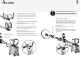
12 Assembly 13 Attaching the Waistbelt to the Battery Harness: 1 Place the belt on a flat surface with the studs facing up. Ensure that all the studs are unclipped. 2 Place the harness on top of the belt, with the battery pouch facing up. Press the belt studs over the harness strap to hold the belt in place. 3 Turn the harness and waistbelt over so that the pouch faces downwards. 4 Clip the shoulder strap buckles together. Connecting the Battery Pack: 1 Place the battery into the battery harness pouch.
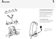
14 Assembly 15 Attaching the Bungy Cord: 1 Create a loop in the bungy cord. 2 Undo the plastic wing-nut and remove the bolt from the clamp. 3 Push the bolt back through the clamp and loop to secure the bungy cord to the shaft. 4 Fasten the screw with the wing-nut. Fitting the Battery Harness: 1 Thread your arms through the harness, so the battery pack sits on your back. 2 Clip the waist and chest buckles together. Adjusting the Detector for Comfortable Detecting, pg. 16.
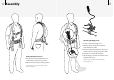
16 Adjusting the Detector for Comfortable Detecting For comfortable, long term detecting, it is important that you take the time to adjust the detector correctly. 17 Holding the Detector: Thread your arm through the armrest and strap. Grasp the handle of the detector and rest your forearm in the armrest. Adjusting the Position of the Handle: Your elbow should sit just above the back of the armrest and you should comfortably grip the handle. Slide the handle into position.
18 Charging the Battery The aluminium battery case contains the 7.4V Lithium Ion battery pack and an internal charging circuit. Supplied with the GPX-4000 is a mains charger adaptor and a 12V vehicle charger adaptor. When fully charged, the battery will provide enough power to operate the detector for 12+ hrs. A spare battery is available as an accessory. If travelling into remote areas, a spare battery will ensure you can continue detecting for long periods of time.
20 Battery LED Patterns Taking Care of Your Battery Routine Brief cycling red-orange-green: Occurs once (or a few times) when the detector is turned on or when a new battery is connected The Lithium Ion battery is specifically designed for the GPX-4000. Very brief orange blink: Beginning of charge Solid orange: First phase of charge The Lithium Ion battery is not compatible with previous detectors and for this reason it is supplied with a power lead with non-compatible plugs.
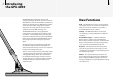
22 Detecting Basics The GPX-4000 is a ‘motion’ detector. This means it must be moving over a target to detect it. The GPX-4000 will perform at its best when the coil is kept close and parallel to the ground at all times. This will increase detection depth and response to small objects. Practise sweeping the coil over the ground in a side-to-side motion, while walking forward slowly at the end of each sweep. Slightly overlap the previous sweep to ensure full ground coverage.
24 Front Control Panel Rear Control Panel Auto Tune automatically reduces electrical interference. (pg. 33) Coil Connector Connects the coil to the control box. Threshold is the constant background audio produced by the detector. This control increases / decreases the level of the Threshold. (pg. 34) Smart Point is a connection point for the Quick-Trak button, located on the handle.
26 Turning the Detector On The On / Off button is located on the back control panel. To turn the detector on or off: Press and release On / Off. Function Select Setting On/Off Hold for FP It is best to only turn the detector on when outdoors and away from sources of electromagnetic disturbance such as power lines, transmitters, electric fences and phone towers. These sources may cause the detector to perform erratically, giving numerous false signals.
28 Search Mode Search Mode Patch G Deep The GPX-4000 has 3 separate Search Modes: General (G), Patch & Deep. Each Search Mode has a series of Factory Preset settings saved, which can also be customised with personal preferences to suit different detecting conditions. 29 G Deep Selecting the Search Mode To begin detecting, select the desired Search Mode that best suits the style of detecting you intend on doing.
30 Factory Presets The GPX-4000 is provided with a Factory Preset FP selection of menu settings, suitable for first-time users. Main Menu: Range: Factory Preset: Volume Limit 1 to 40 25 Audio Tone 1 to 100 50 Signal Peak 1 to 20 15 Track Speed Slow Medium Fast Medium 2 Press and hold On/ Off until the Reset Defaults menu appears (approx. 5-6 seconds). GB Type General Specific General 3 Turn Function Select to the right to select All Settings, as shown on the diagram.
32 Tune Reducing Electrical Interference Auto Tune The detector may become noisy due to electrical interference from powerlines, radio transmitters electrical equipment or other detectors operating close by. The detector interprets this interference by the Threshold becoming erratic.
34 Threshold Adjusting the Background Audio Level Threshold is the constant audible background audio tone or 'hum' produced by the detector. Threshold The level of the Threshold should be set low, but still audible and stable. Ideally it should be a smooth, gentle hum. 35 When the Threshold is too high, a faint signal is masked, and only the peak of the loud signal is audible above the Threshold.
36 Soil/Timings Optimising the Detector for Different Soil and Target Types Soil / Timings Sensitive N Salt Sensitive The Soil/Timings switch has the ability to change the electronic 'timing' or pattern of the pulses. This optimises the detector for different soil conditions, the type of coil being used and desired target sizes. Soil/Timings can make a big improvement to your finds.
38 Ground Balance Reducing Ground Noise Ground Balance Fixed Tracking The ground contains not only sand, but also many different chemicals, minerals and salts. These extra materials are referred to as ground mineralisation. This ground mineralisation may often produce erratic sounds, known as ‘ground noise’. The Ground Balance function minimises the ground noise while retaining maximum sensitivity to metal targets.
40 Ground Balance Procedure for Tracking 41 (For Ground Balance Type – General) Fixed 1 Find a clear area of ground without any targets. Ground Balance re-set in Tracking 2 Change the Ground Balance switch to Fixed. Whilst sweeping the coil, you can test if you are still in harmony with the ground by stopping, and raising and lowering the coil – if the Threshold remains stable then you are still Ground Balanced.
42 Ground Balance Procedure for Fixed 43 (For Ground Balance Type – General) 1 Find a clear area of ground without any targets. Fixed 2 Change the Ground Balance switch to Fixed. 3 Whilst keeping the coil parallel to the ground, lower and raise the coil between 25mm and 100mm (1" and 4") over the ground. Try to lower the coil as close to the ground as possible without touching it. 4 While moving the coil, press and hold the Quick-Trak button.
44 Coil/Rx Changing the Sensitivity and Receive (Rx) Fields of the Coil Coil / Rx 45 Coil/Rx allows you to change the sensitivity and search patterns of receive (Rx) fields of the coil. Double D The GP series or Commander Range of Double-D coils can change characteristics to suit different detecting conditions and targets. M Coils not specifically designed for the GPX-4000 may behave erratically or be ineffective in either Monoloop (M) or Cancel.
46 Functions Settings The Function Select control scrolls through a list of functions. 47 Once a function has been selected, the Setting control accesses a settings adjustment screen. Title indicates what type of function you are viewing (general or mode dependant). Navigation Arrows indicate which way the menu can scroll Functions There are two types of functions, general functions (under the Main Menu heading) and mode dependant functions (under the Mode Edit heading).
48 Accessing Functions Function Select Setting Function Select Turn the Function Select control right to scroll down the list. The currently selected function is highlighted. Accessing Settings Setting Turn the Function Select control left to scroll up the list. The currently selected function is highlighted. Function Select Setting With a function highlighted, turn the Setting control to the left or right to adjust the setting.
50 Volume Limit Setting the Maximum Volume of all Sounds Range Factory Preset 51 1 to 40 25 Volume Limit is the maximum level of sound emitted by the detector when a target is detected. If the Volume is set to maximum, all target signals will be heard and will sound proportional to the target size and depth. Maximum limit allows you to hear the difference between a small and large target, but may be uncomfortable to your hearing if a large target is found close to the coil.
52 Audio Tone Adjusting the Pitch of the Threshold Range Factory Preset Signal Peak Adjusting the Pitch Variation of Target Signals 1 to 100 50 Range Factory Preset Tone is the pitch of the Threshold emitted by the detector. 53 1 to 20 15 You are more likely to hear a target signal when both the volume and the tone of the target signal change upon detection rather than the volume alone. Large, deep targets produce a different response to small shallow targets.
54 Tracking Speed Keeping up with Changing Ground Sensitive Soil/Timings 55 (Ground Balance, pg. 40) Range Factory Preset Ground Balance Fixed Tracking Slow, Medium, Fast Medium When searching in highly variable mineralisation, Tracking Ground Balance is the preferred setting. Tracking Ground Balance automatically adjusts the Ground Balance as necessary to maintain stability and detection depth. The GPX-4000 has three Auto Tracking Speed options: Slow, Medium & Fast.
56 Ground Balance Type Ground Balance Procedure for Specific (Ground Balance, pg. 38) Range Factory Preset 57 Specific, General General General This is the best Ground Balance Type for use in over 90% of goldfield soils and uses the conventional automatic Tracking on the previous Minelab model, the GP3500. In Tracking, General Ground Balance samples variations in the ground mineralisation and sets a continuously changing average of the Ground Balance level.
58 Iron Reject Off (All Metal) Accepting all Targets Types Range Factory Preset 59 Off (All Metal), 1 to 30 Off (All Metal) The GPX-4000 is capable of rejecting many iron/ ferrous targets while still detecting non-ferrous targets. While detecting in littered goldfields, much of the iron rubbish may be ignored, with a high probability that valuable targets will not be missed. When Iron Reject is turned off , no iron targets will be rejected, therefore all types of metals will produce a target response.
60 Iron Reject Rejecting Iron Targets Range Factory Preset 61 Off (All Metal), 1 to 30 Off (All Metal) There is usually some merging of characteristics between targets that are clearly ferrous and others that are ‘maybe’ ferrous. Iron Reject allows you to make fine adjustments in the determination of the ‘maybe’ signals. Iron Reject will give the best results when used in combination with the specially designed GP Series or Commander DoubleD coils and will not work when using Monoloop coils.
62 Battery Test Viewing the Battery Voltage Manual Tune Reducing Electrical Interference 63 (Auto Tune, pg. 33) Range Manual Tune allows you to select a particular channel, or you may want to fine tune the detector after performing an auto-tune. If detecting in a quiet area with no interference, you may find that you can select a channel at one end of the scale or the other. Low numbers are lower frequency channels and high numbers are higher frequency channels.
64 Audio Type Changing the Audio Response of Target Signals Gain Adjusting the Sensitivity of the Detector Range Normal, Quiet, Boost, Deep Factory Preset Patch Boost General Normal Deep Deep Range Factory Preset The Audio Type function replaces the Boost switch on the previous GP Series detectors. There are four options to choose from. Each setting changes the way that the detector interprets a signal and how that signal is produced as an audio response.
66 Motion Adjusting Sweep Speed Range Factory Preset 67 Very Slow, Slow, Medium, Fast Patch Med General Slow Deep V. Slow The speed at which you sweep the coil has an effect on target response time and Ground Balance adjustment. Matching your preferred coil sweep speed with the corresponding Motion setting can reduce noise. Very Slow and Slow When carefully detecting a small area, a slow Motion setting will allow for maximum depth and sensitivity to small targets.
68 Response Inverting the Pitch of the Target Signal Range Factory Preset 69 Normal, Inverted Patch Normal General Normal Deep Inverted The Response function allows you to invert the normal pitch combination of target signals to different size targets.
70 Pinpointing Locating the Target 71 To find an object and reduce the size of the hole required to remove it from the ground, it is necessary to pinpoint the exact location of the object. When a target is detected, sweep the general area with the coil, taking note of where the strongest signal is received. By shortening the length of the sweep it should be possible to draw an imaginary line in the ground where the strongest signal is located.
72 Recovering the Target 73 It is essential to carry at least one of the following digging tools with you when searching: - a small, strong digging spade or shovel - a pick with broad scraping blade - a crowbar (for very deep objects in hard ground). Backfill Every Hole You Dig Always refill any holes and scatter leaves, before leaving the area. Help restore the area to its original condition. Any rubbish you recover should be taken away with you and disposed of properly.
74 Detecting Tips Follow these hints and techniques for better detecting and happy prospecting that will help you to utilise the power of your GPX-4000. Identifying Target Signals • For Maximum Gold Recovery Keep the coil as close to the ground as possible. • Listen carefully. This is more important than looking. Slow down, do not rush, take your time.
76 Commander Coils The GPX-4000 is supplied with the 11" Double-D coil. This coil has an excellent combination of depth, sensitivity and stability. 77 In addition to this there are also a number of other size coils now available to give improved performance to your detector. These range from smaller coils which give greater sensitivity to small targets and are lighter and manoeuvrable in heavy vegetation, up to larger coils which give greater depth.
78 Choosing the Right Coil for the Job There are five main things that you should consider when deciding which coil is best for your terrain and target: In some circumstances, non Minelab Double-D and Monoloop coils will work on the GPX-4000. However, there are limitations which means that some functions will not work properly. In some cases the use of coils not designed for the GPX-4000 may cause the detector to be unstable and noisy.
80 User Preferences Main Menu: Range: Volume Limit 1 to 40 Audio Tone 1 to 100 Signal Peak 1 to 20 Track Speed Slow Medium Fast Troubleshooting User Preferences: No sound • Check that the detector is on (battery, power cable, connections and LCD) • Turn the Threshold control fully clockwise • Turn the Volume Limit to maximum (40) • Check that the headphones are plugged in • Try using a different set of headphones or a different battery GB Type General Specific Threshold but no target signa
82 Glossary of Terms Control Box This encloses the electronic circuitry of the detector. The control box generates the Tx (transmit) signals sent by the coil and processes the Rx (receive) signals detected by the coil. All user selectable functions are located on the front and rear panels of the control box. Discrimination The ability of a detector to determine if a located target is made from ferrous metal (iron or steel) or non-ferrous metal (non-magnetic).
84 Glossary of Terms (Continued) Taking Care of Your Detector (Taking Care of your Battery, pg. 21) Salt Mineralisation Salt content in the ground causes a negative (–) response rather than the positive (+) response of laterite soils. A large salt content in the ground will have a different effect on the detector than other types of mineralisation. Therefore the detector needs to use different filtering techniques to overcome this effect.
86 Technical Specifications Detector Transmission Bi-Level Pulse Induction Technology MPS Dual Voltage Technology Coil (Standard) 11" Round Double-D Audio Output 6.35mm (¼") headphone socket Headphones supplied LCD 64x128 pixels Non-backlight reflective Length Extended: 1300 mm Unextended: 1100 mm Weight Including 11" Coil, (Excluding Battery and Accessories) 2.
Service Repair Form Today’s Date Detector / Model Serial Number Purchased From Purchase Date Faulty Part(s) Owner’s Name Address Telephone ( Fax ( ) Day Home ) Email Description of Fault cut out or photocopy Please explain how we can replicate the problem in order to fix your detector.