Adaptto E-drives Lab. 2013 Adaptto E-drives Lab MAX-E, MINI-E Instruction manual Software version: 1.
Adaptto E-drives Lab. 2013 Table of Contents 1. Getting started 2. Main screen 3. Menu and functions 4. Info and error messages 5. Health Monitor screen 6. Stats\Watt-meter screens 7. Connectors and pin-outs 8. Charging and DCDC mode connection 9.
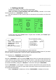
Adaptto E-drives Lab. 2013 1. Getting started To make your e-bike go, you need to follow several steps: Connect controller to your motor, batteries and throttle\e-brake. There is no need to match hall\phase wires while connecting controller to the motor because controller has function. After all connections is done, and the power is connected to the controller you will see the main screen: To enter main menu press “Down” button. If Quick menu is enabled, press “Down” again.
Adaptto E-drives Lab. 2013 After halls and phase configuration is set up and angles are calibrated it is time to set current limits for each profile.
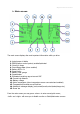
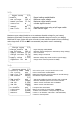
Adaptto E-drives Lab. 2013 2. Main screen The main screen displays the most important information while you drive: 1. Actual power in Watts 2. TCS (traction control system) enabled\activated 3. Current in Amps 4. Smart-Range data (when enabled) 5. Battery SOC in % 6. Speed units 7. Battery “fuel” gauge 8. Speedometer 9. Estimated remaining rage at current SOC 10. Current trip distance 11. Battery voltage 12. Motor temperature (when temperature sensor connected and enabled) 13.
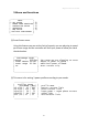
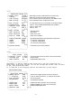
Adaptto E-drives Lab. 2013 3.Menu and functions --------------------| Menu | |> SET RANGE | | POWER MODE PROFILES| | CONTROLLER SETUP | | INTERFACE | | BMS SETUP | | Activate SmartPower | | | --------------------- 1) 2) 3) 4) 5) (1) Smart Power menu. Using this feature you can set the limit of capacity you are planning to spend per known range and the controller will limit your power to allow you reach the destination. --------------------| SmartRange setup | |>Range 010.0Km| | Power amount 04.
Adaptto E-drives Lab. 2013 (3) Main Setup --------------------| SETUP 1/3| |>Speed ratio: 085.4 | mm per electric revolution (speedometer calibration) | Autodetect | autoset halls\phase wires combination | Direction + | if your wheel rotates backwards, change the direction | Calibration |3.1) | 2/3| | Regen settings |3.2) | Charge settings |3.3) | Traction settings |3.4) | Advanced settings |3.5) | 3/3| | DCDC setup |3.
Adaptto E-drives Lab. 2013 3.2) --------------------| Regen Setup 1/2| |>Enable ON | | Max Voltage 100 V| | Rated Current 35.2A| | Inversion N | | 2/2| | Smooth NO | | PWM limit 95.
Adaptto E-drives Lab. 2013 3.5) --------------------| Advanced setup 1/5| |>Angle corr. -4.99°| | Timing +034uS| | Ind timing 0628uS| | PWR timing +0.53 | | 2/5| |>OVS timing 007° | |>Termosensor YES | | TSensor type KTY84 | | T° limit 180°C | | 3/5| |>Hall Offset 300° | | Hall Reverse NO | | Wire Reverse YES | | Wire R, mOhm 100 | | 4/5| | ControlMethod SLESS | | SIN5X 0000 | | SIN7X 0000 | | SIN11X 0000 | | 5/5| |>System Reset | | | --------------------3.
Adaptto E-drives Lab. 2013 4.
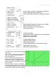
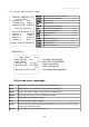
Adaptto E-drives Lab. 2013 5.Health Monitor There are several parameters that could be useful for controller setup and diagnostics. First string: important controller voltages. Second string: motor hall sensor voltage. Third string: motor temperature. Forth string: hall sensors positions. Fifth string: service information and protection. Last string: internal controller temperature. 6.
Adaptto E-drives Lab. 2013 7.
Adaptto E-drives Lab. 2013 8.Charging and DCDC mode connection To charge your battery via regen-charging mode you must connect PSU (Power Supply Unit) to the controller via Inductor according to the following picture. Inductor L1 must be 15-30uH with sufficient current rating (>than PSU max current) Capacitor C1 must be 470-1000uF with voltage greater than PSU voltage Left side of L1 connected to ANY of 3 phase wires, while they still must be connected to the motor.
Adaptto E-drives Lab. 2013 10.