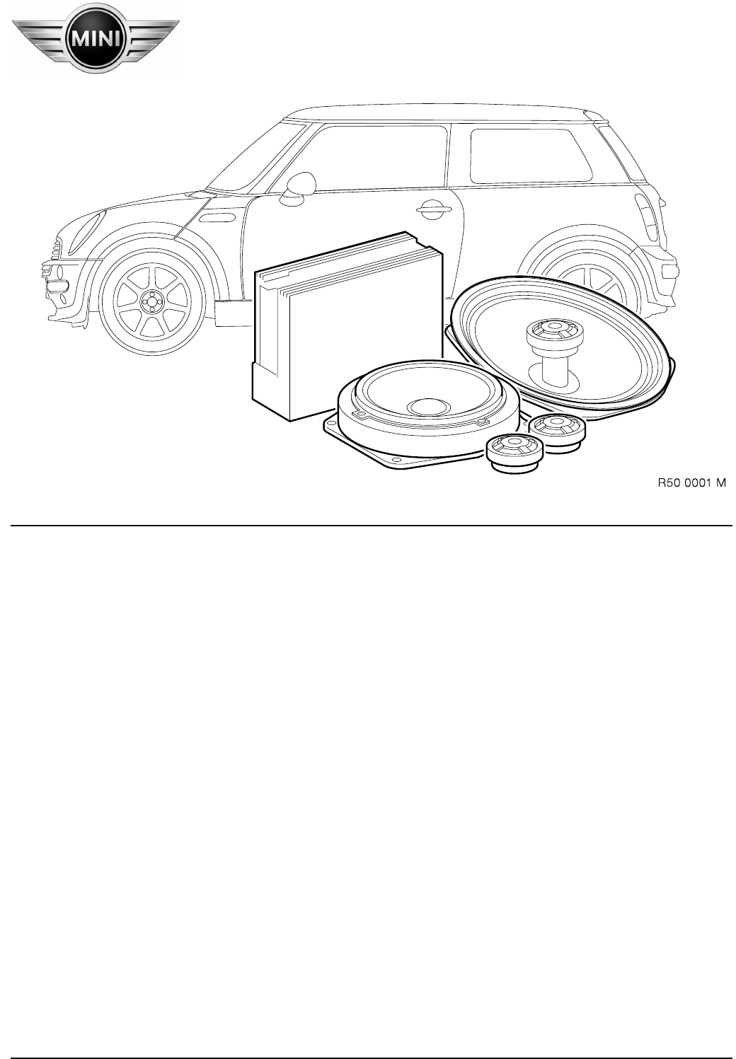
Parts and Accessories Installation Instructions Installation kit, sound module MINI (R50/R53) Left-hand drive (LHD) Not suitable for vehicles with on-board monitor radio Not suitable for vehicles with "NG*" car radio Not suitable for vehicles with SA 674 ("harman/kardon" HiFi system) The installation time of approx. 2.5 hours can vary depending on the condition and equipment of the vehicle. Retrofit/installation kit No. 82 83 0 136 491 * New Generation Retrofit/installation kit No.
Contents Section Page Important Information. . . . . . . . . . . . . . . . . . . . . . . . . . . . . . . . . . . . . . . . . . . . . . . . 3 1. Preparation . . . . . . . . . . . . . . . . . . . . . . . . . . . . . . . . . . . . . . . . . . . . . . . . . . . . . . . 4 2. Schematic installation and routing diagram . . . . . . . . . . . . . . . . . . . . . . . . . . . . . . . 5 3. Connection overview, adapter lead and power cable . . . . . . . . . . . . . . . . . . . . . . . . . 6 4.
Important Information Read out the defect code memories before disconnecting the battery and on completion of assembly. It is possible that the connections and/or pin assignments change during the course of further development. For this reason, the currently valid ETM (Electrical Troubleshooting Manual) must always be used for installation purposes. Jumpers, double crimp connections or parallel connections will be required if the specified pin chambers are occupied.
1. Preparation 0 Carry out quick test Disconnect negative terminal of battery The following components must be disassembled or removed beforehand: Battery with battery box Instrument cluster Radio Front left door trim panel Front right door trim panel Remove woofers/mid-range speakers in front doors (no longer required) Release rear left side trim panel in front area Release rear right side trim panel in front area Remove speakers in rear side sections (no longer required) Retrofit/installation kit No.
2. Schematic installation and routing diagram 0 Key 0 1 2 3 4 5 6 7 8 9 10 Amplifier Fuse (20 A) Power cable with fuse holder at B+ (see B2 on Page 6) Adapter lead Woofer/mid-range speaker Tweeter Coax speaker Car radio connector Connector for standard wiring harness Vehicle ground connection (see A3 on Page 6) Retrofit/installation kit No.: 82 83 0 136 491 Installation instruction No.: 01 29 0 139 395 Status: 06.
3.
4. Installing and connecting adapter lead and power cable 0 0 As illustrated, install adapter lead A as follows: Route branch A 1 and A 2 to installation location of radio. Route branch A 4 to place of installation of instrument cluster. Route branch A 3 and A 5 through rubber grommet (1) into engine compartment and use sealing compound to seal off rubber grommet (1) from engine side.
5. Installing amplifier 0 0 Unscrew Torx screws (1). Remove connector (2), white 18-pin connector housing, together with retaining fixture from carrier (5). Remove sticker (3) and clean adhesion point with spirits. Cut out mounting bracket for controls (4) in marked area (arrows)!3 0 0 Disconnect connector (2), white 18-pin connector housing, and route behind strut (1). Reconnect plug connection and use cable strap to secure connector (2) in a suitable position.
5. Installing amplifier 0 0 Do not soil adhesive surface of adhesive strip (3) when installing amplifier (1). 3 Install amplifier (1) as illustrated, turn into horizontal position and push upward. Route wiring harness (2) up to amplifier (1). 0 0 Firmly secure amplifier (1) and struts (3) with existing Torx screws (4) on carrier (2). Press amplifier (1) with adhesive strip (5) onto carrier (2) and adhere in position. It must be possible to install and secure the instrument cluster free of stress.
6. Installing tweeters and woofers/mid-range speakers at front 0 0 0 0 The figures show the working steps on the left-hand side of the vehicle. The same procedure is to be followed analogously on the right-hand side of the vehicle. 3 Unclip standard tweeter (1) from mounting bracket (2) and unplug connector (3) (standard tweeter is no longer required). Remove screw (5) and release screw (4). 0 Fit tweeter (1) in mounting bracket (2) and firmly tighten with screw (5).
7. Installing rear coax speakers 0 0 The figure shows the working steps on the left-hand side of the vehicle. The same procedure is to be followed analogously on the right-hand side of the vehicle.3 Connect plug connector (3) to coax speaker (1). Firmly tighten coax speaker (1) with existing screws (2). 0 Retrofit/installation kit No.: 82 83 0 136 491 Installation instruction No.: 01 29 0 139 395 Status: 06.2001 Adhere foam seal (1) onto coax speaker (2) as illustrated.
8. Affixing stickers Install front left and right door trim panels. Install rear left and right side trim panels. 3 It is important to precisely observe the following procedure for affixing the stickers to ensure they remain adhered permanently. 1. The speaker covers must be dry, clean, free of dust and grease. The temperature during the adhesion process must be at least 15 ûC. 2. Clean the surfaces to be adhered with spirits. 3. Allow cleaned surfaces to air for approx. 15 minutes. 4.
9. Concluding jobs/encoding Connect battery. Carry out function check. Reassemble vehicle in reverse order of removal. This system does not require encoding. 1 0 . Start-up After switching on the radio, the volume control on the radio control panel should be set to a low volume to ensure an extremely high volume level is not set after the delayed cut-in of the sound module amplifier! 3 The sound module is equipped with a switch-on delay facility in order to avoid damaging the audio system.