IP Control User Guide w w w . m i n i c o m . c o m International HQ North American HQ European HQ Jerusalem, Israel Linden, NJ, USA Dübendorf, Switzerland Tel: + 972 2 535 9666 minicom@minicom.com Tel: + 1 908 486 2100 info.usa@minicom.com Tel: + 41 44 823 8000 info.europe@minicom.com Technical support - support@minicom.com 5UM70166 V1.
IP CONTROL Table of Contents 1. Welcome ...................................................................................................................... 3 2. Introduction ................................................................................................................. 4 3. Key features ................................................................................................................ 4 4. System components...................................................................
USER GUIDE 23.6 Power cycle ..................................................................................................................................... 26 23.7 Keyboard key sequences ............................................................................................................... 26 23.8 Synchronizing mouse pointers ....................................................................................................... 27 23.8.1 Aligning the mice pointers .............................
IP CONTROL 1. Welcome Thank you for buying the IP Control system. This system is produced by Minicom Advanced Systems Limited. This document provides installation and operation instructions for Minicom’s IP Control. It is intended for system administrators and network managers, and assumes that readers have a general understanding of networks, hardware and software.
USER GUIDE 2. Introduction The IP Control extends your KVM (keyboard, video, mouse) from any computer or server over TCP/IP via LAN, WAN or Internet connection. Now you can control, monitor and manage your servers from wherever you are, inside or outside the organization. The IP Control is a cost-effective hardware solution, for secure remote KVM access & control of a computer/server from the BIOS level independent of the OS.
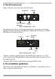
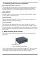
IP CONTROL 5. The IP Control unit Figure 1 illustrates the front panel of the IP Control. Monitor Keyboard LAN LAN (Ethernet) connector Mouse Figure 1 IP Control ports – side 1 For (optional) local access to the connected computer you connect a keyboard, monitor and mouse to the above KVM ports. Connect the IP Control to a 10/100 Mbit Ethernet using the LAN port. KVM In Serial Go Local button Power KVM In Serial Go Local 3.
USER GUIDE 6.1 Avoiding general rack mounting problems Elevated operating ambient temperature The operating ambient temperature of the rack environment may be greater than the room ambient when installing into a closed or multi-unit rack assembly. So install the equipment in an environment compatible with the maximum rated ambient temperature. Reduced airflow Install the equipment in a rack in such a way that the amount of airflow required for safe operation is not compromised.
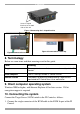
IP CONTROL Screw L-shaped brackets to 1 or both sides of the unit Figure 4 Connecting the L-shaped bracket Figure 6 Connected to a table top Figure 5 Connected to a rack 8. Terminology Below are some terms and their meanings used in this guide. Term Meaning Target server The computers/servers that are accessed remotely via the IP Control.
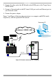
USER GUIDE 2. Connect the other end of the KVM cable to the KVM ports of the Target Server / KVM switch. 3. Connect a Network cable to the IP Control LAN port and to an Ethernet port on your Network switch. 4. Connect the power adapter. Figure 7 and Figure 8 illustrate the connections to a computer and KVM switch respectively, with the optional KVM console. User over IP Internet / WAN / LAN P110 SD LAN MINICOM Target PC IP CONTROL KVM cable KVM In Serial 3.
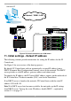
IP CONTROL User over IP Internet / WAN / LAN P110 KVM switch SD SERIA MOUS L E POWE R K B STATION 2 P MOUS /2 S E SCREE N C OMPU TER 5 C OMPUTER 6 C OMPU TER 1 C OMPU TER 2 C OMPU TER 7 C OMPU TER 3 C OMPU TER 8 C OMPU TER 4 KVM cable Pro Lia nt DL36 0 9.1 - GB 10k ULT RA2 SCSI 9.1 - GB 10k ULTRA2 SCSI Pro Lia nt DL36 0 LAN 9.1 - GB 10k ULT RA2 SCSI MINICOM 9.1 - GB 10k ULTRA2 SCSI Pro Lia nt DL36 0 9.1 - GB 10k ULT RA2 SCSI 9.1 - GB 10k ULTRA2 SCSI Pro Lia nt DL36 0 9.
USER GUIDE Unit boots up Device network setting is set to obtain IP address from DHCP Server Yes Every 5 minutes Is DHCP Server present in the connected LAN? No Device IP is: 192.168.0.155 No Yes IP address is assigned by the DHCP server No To access the configuration page of the unit, open IE 6.
IP CONTROL 12. Logging into the Web interface Complete the initial setup via the Web configuration interface: 1. Open your Web browser (Internet Explorer version 6.0 or higher). 2. Type the IP Control system IP address - https://IP address/config - and press Enter. The login page appears, see Figure 10. Figure 10 Login page 3. Type the default Administrator user name admin and password access (both lower case). 4. Press Enter. The Web interface opens at the Network Configuration page. See Figure 11. 5.
USER GUIDE 12.1 SSL Certificate notes When first connecting to IP Control’s configuration page, 2 browser security warnings appear. Click Yes to proceed. The first warning disappears upon first IP Control client installation, when Minicom’s root certificate is installed. 13. Network > Configuration Consult your Network Administrator for the network settings. Device name - Type a name for the IP Control. Default device name consists of the letter ‘D’ followed by the 6-digit device number (D.N.
IP CONTROL 13.2 KVM.net KVM.net is a centralized IP based system for secure control of servers and network devices, power and user administration in the data center environment. KVM.net combines Out-Of-Band, KVM via IP access with modern IT standards and requirements. It is the most comprehensive remote server maintenance solution available in the market today. Enable KVM.net - Check this option to allow IP Control to be remotely managed by Minicom’s KVM.net system.
USER GUIDE 15. Administration > User Settings From the menu click User Settings, Figure 13 appears. Figure 13 User Settings On this page an Administrator creates and edits users. There are 3 levels of user access: • Administrator • User • View only Administrator An Administrator has unrestricted access to all windows and settings and can “take over” any active session (explained in section 23.1 on page 22). An Administrator can change the name and password of all users.
IP CONTROL 15.1 Adding a user To add a user: and type a name and a password. The password must be at 1. Click least 6 characters – letters or numbers, and must not include the user name, even if other characters are added. Note! The following “special” characters: &, <, >, ” cannot be used for either the user name or password. Depending on the security level chosen the user name and password parameters are different. See section 18 on page 18. 2.
USER GUIDE 16. Administration > Switch Configuration When a KVM switch is connected to the IP Control system, you must configure the switch parameters. To do so: 1. From the menu click Switch Configuration. The KVM Switch Configuration window appears, see Figure 14. Figure 14 Switch Configuration 2. Choose the manufacturer and model of the connected KVM switch. The number of possible connected servers appears in the Server Name section. 3.
IP CONTROL 17. Administration > Serial Settings Where you have a Serial device connected to the system you must configure the RS232 settings. To do so: From the menu click Serial Settings, the Serial Settings appear, see Figure 15. Figure 15 Serial Settings Type a device name and choose the correct device parameters. Note! Where you have a Minicom Serial Remote Power Switch connected, see below Assign to RPS. 17.
USER GUIDE 18. Security > Settings Configure the security features, such as Account Blocking, Password Policy and Idle Timeout, as explained below. From the Security section click Settings, the Security Settings appear, see Figure 16. Figure 16 Security Settings The security Settings elements: Account Blocking – decide on the number of attempts to login with a wrong username or password after which there is a time lock or a total block.
IP CONTROL Figure 17 Install SSL Certificate page Certificate File - Browse to locate the cer file. Private File - Browse to locate the private key file in Microsoft pvk format. Key Password - Type the “private key” password. Click . 20. Maintenance > Firmware Upgrade Upgrade the IP Control firmware to take advantage of new features. Download the firmware from Minicom’s website at: http://www.minicom.com/phandlh.htm. Save the firmware file on the Client computer. From the menu select Firmware Upgrade.
USER GUIDE Note! Depending on the type of firmware upgrade, the following settings may be erased: User settings, KVM switch settings, mouse and video adjustments and RS232 settings. For more information refer to the firmware release notes. The network settings remain intact. 21. Restore Factory Settings You can restore the IP Control unit to the factory settings.
IP CONTROL 23. Starting a remote session Windows Vista Note! To login to the web interface with Windows Vista, run Internet Explorer as Administrator. To do this, right-click the Internet Explorer icon on the Taskbar and select Run as administrator. See Figure 20. Figure 20 Select Run as administrator At a Client computer open Internet Explorer (6.0 and above) and type the IP Control’s IP address. https://IP address. The Login page appears. Type your username and password and press Enter.
USER GUIDE Figure 21 Remote session window 23.1 Taking over a busy remote session When connecting to a busy Target Server an Administrator has the option to take over the Target Server. A User only has this option when the current session is run by another User, but not by an Administrator. The following message appears Figure 22 Busy remote session options Choose to Take Over or View Only or Cancel. 23.
IP CONTROL To minimize the Toolbar: Click the arrow . Click again to maximize the Toolbar. 23.3 Switching to a different server/device To connect to a different server/device: 1. From the Toolbar, click servers/devices appears. , or right-click . A list of connected 2. Click the desired server or Serial device. The screen of the server or the Serial device window appears. 23.4 Changing the performance settings In a LAN environment, it is best to leave the bandwidth setting on High.
USER GUIDE Medium - Select medium for medium compression and 256 colors. Medium is recommended when using a standard internet connection. High - For optimal performance when working on a LAN, select High. This gives a low compression and high colors (16bit). Custom – You can choose your own compression and color levels. Click OK. The chosen setting take effect and the screen of the last accessed Target Server appears. 23.
IP CONTROL Figure 24 Manual Video Adjustments controls Brightness / Contrast - use the scales to adjust the brightness and contrast of the displayed image. Move the sliders to change the displayed image. Click in the area of the sliders for fine-tuning. For the following controls choose the appropriate measurement. Horizontal Offset - defines the starting position of each line on the displayed image. Vertical Offset - defines the vertical starting position of the displayed image.
USER GUIDE 23.6 Power cycle Where a Minicom Remote Power switch is connected to the Serial port of the IP Control, you can power manage the Target servers as follows: . The Power menu appears, see below. From the Toolbar, click Figure 25 Power menu To send a power cycle command or to power down or up the currently accessed Target server, select the appropriate option.
IP CONTROL 2. Select the desired sequence and click OK. The sequence appears in the Special Key Manager box. 3. Click OK. The sequence appears in the Keyboard Key sequence list. To record a key sequence: 1. From the Special Key Manager box press Record New. The Add Special Key box appears see Figure 19. Figure 27 Add Special Key box 2. Give the key sequence a name in the Label box. 3. Click Start Recording. 4. Press the desired keys. The keys appear in the area provided. 5. Click Stop Recording. 6.
USER GUIDE Warning Before synchronizing mouse pointers adjust the video of the Target Server, (explained above) otherwise mouse synchronization may not work.. 23.8.1 Aligning the mice pointers When accessing the Target Server, the mice may appear at a distance to each other. To align the mouse pointers: From the Toolbar click align. / Align or press Ctrl+M simultaneously. The mice 23.8.2 Calibrating mice pointers A Target Server may have a different mouse pointer speed to the Client computer.
IP CONTROL Figure 28 Mouse Settings box 2. Select the Target Server’s Operating System and click OK. Instructions and sliders appear. 3. Follow the instructions and set any relevant sliders to the same values as set in the Target Server’s Mouse Properties window. 2 examples! For Windows XP, go to the Mouse settings on the Target Server and uncheck Enhance pointer precision. For Windows NT4.
USER GUIDE Figure 29 Mouse Emulation box Select the mouse connected to the Local Console port on the IP Control, e.g. if the local mouse is a non-Microsoft 2 button mouse, select Standard Mouse and uncheck Microsoft Mouse. Max Rate - this defines the maximum mouse report rate. For Sun Solaris the default value is 20 in order to support older Sun versions. 23.9 Minicom logo menu features , a menu appears. From this menu you can Right click the Minicom logo access the connected devices.
IP CONTROL 23.10 Full screen mode Work on the Target Server as if you are working on a local computer, with full screen mode. To work in full screen mode: 1. Ensure that the Client computer has the same screen resolution as the Target Server. 2. Press F11. The Internet Explorer window disappears, leaving the Internet Explorer menu bar at the top. 3. Right click the Internet Explorer menu bar and check Auto-Hide. The Internet Explorer menu bar disappears. You are in full screen mode.
USER GUIDE 2. Wait until the unit finishes booting (1-2 minutes). 3. You need to know the IP address of the IP Control. The IP address depends on whether there is a DHCP server on the network. If there is, the DHCP server assigns an IP address to the IP Control. If there is no DHCP server, the unit boots with the static IP address 192.168.2.155. See Figure 31 for an overview of this procedure.
IP CONTROL Figure 33 Safe mode menu 24.2 Restoring factory defaults To restore factory defaults: 1. From the menu choose Restore Factory Settings. A warning appears see Figure 34. Figure 34 Warning 2. Click . A further warning appears, see below. Figure 35 Warning 3. Click OK, the factory defaults are restored. When the process finishes Figure 36 appears. Figure 36 Reboot 4. Click Reboot to restart the unit.
USER GUIDE 24.3 Restoring the device firmware Contact Minicom Technical Support support@minicom.com, to receive the Upgrade firmware required to restore the device firmware. Save the Upgrade firmware on the hard disk of a computer connected to the network. To restore the device firmware: 1. From the Safe mode menu choose Firmware Upgrade. 2. Locate the Upgrade firmware and click Install, then click Start Upgrade. The firmware upgrades. When the process finishes Figure 37 appears. Figure 37 Reboot 3.
IP CONTROL 25. Technical specifications Target Server DOS, Windows, Novell, Linux, SUN Solaris for PC Operating systems Client Computer Windows 2000 or higher with IE 6.
USER GUIDE 26. Video resolution and refresh rates Hz → 56 640x480 60 65 66 70 72 x x x x x x x 720x400 800x600 73 75 76 1024x768 x x x 86 x x x 85 x x x 1152x864 x x x x x x 1152x900 x 1280x720 x 1280x768 x 1280x960 x 1280x1024 x 1600x1200 x x x x x X x x x x x x 27. Safety The device must only be opened by an authorized Minicom technician. Disconnect device from the power source and all cables from the device before service operation! 28.
IP CONTROL Regional Offices Germany France Italy Kiel Vincennes Rome Tel: + 49 431 668 7933 info.germany@minicom.com Tel: + 33 1 49 57 00 00 info.france@minicom.com Tel: + 39 06 8209 7902 info.italy@minicom.com England China Asia Pacific / S. Korea Tel: + 44 121 288 0608 Tel: +86 21 6445 3181 Tel: +972 2 535 9618 info.uk@minicom.com info.china@minicom.com info.ap@minicom.com www.minicom.
USER GUIDE 38