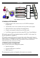
Smart IP Extender User Guide International HQ North American HQ European HQ Italy Jerusalem, Israel Linden, New Jersey Zurich, Switzerland Rome Tel: + 972 2 535 9666 minicom@minicom.com Tel: + 41 1 455 6220 Tel: + 1 908 4862100 info.usa@minicom.com info.german@minicom.com www.minicom.com Tel: + 39 06 8209 7902 info.italy@minicom.com Customer support - support@minicom.com 5UM20104 V2.
SMART IP EXTENDER Table of Contents 1. 2. 3. 4. 5. 6. 7. 8. 9. 10. 11. 12. 13. 14. 15. 16. 17. 18. 19. 20. 21. 22. 23. 24. 25. 26. 27. 28. 29. 30. 31. 32. 33. 34. 35. 36. 37. 38. 39. Welcome....................................................................................................................... 4 Introduction .................................................................................................................5 Features of IP Extender ..............................................
USER GUIDE 40. 41. 42. 43. 44. 45. 46. 47. 48. 49. 50. 51. 52. 53. 54. 55. 56. 57. 58. 59. 60. 61. 62. 63. 64. 65. 66. 67. 68. 69. 70. 71. 72. 73. 74. 75. 76. 77. 78. 79. 80. 81. Status via IPMI ...........................................................................................................27 Event Log via IPMI.....................................................................................................27 Power Control.......................................................................
SMART IP EXTENDER 82. 83. 84. 85. Data file for support ..................................................................................................59 Include/modify custom HTML code .........................................................................59 Access via Telnet ......................................................................................................60 Telnet server commands ..........................................................................................
USER GUIDE 1. Welcome The Smart IP Extender system is produced by Minicom Advanced Systems Limited. Technical precautions This equipment generates radio frequency energy and if not installed in accordance with the manufacturer’s instructions, may cause radio frequency interference. This equipment complies with Part 15, Subpart J of the FCC rules for a Class A computing device.
SMART IP EXTENDER 2. Introduction The Smart IP Extender (IP Extender) from Minicom Advanced Systems redirects local keyboard, mouse and video data to a remote computer. All data is transmitted via IP. IP Extender features, remote KVM access and control via a LAN, Internet, or ISDN connection. IP Extender provides a non-intrusive solution for remote access and control.
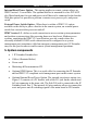
USER GUIDE Smart IPs SMART G I F RESET IP Extender V R E MINICOM SMART G I F RESET IP Extender V R E Administrators MINICOM KVM Matrix switch SMART G I F RESET IP Extender V R E G I F RESET MINICOM SMART IP Extender V R E IP Network MINICOM Figure 2 Multiple users/servers 3. Features of IP Extender • KVM (keyboard, video, mouse) access over IP, ISDN or analogous telephone line.
SMART IP EXTENDER Internal Reset/Power Option - This option applies to remote systems where no IPMI Version 1.5 is available. The optional bracket is mounted in a free PCI/AGP slot. Main board pins for reset and power on/off have to be connected to the bracket. With this option it is possible to perform a remote reset, power cycle, and power on/off. External Power Switch Option - When there is neither a IPMI V1.
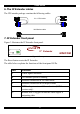
USER GUIDE 6. The IP Extender cables The IP Extender package contains the following cables. 3 in 1 CPU cable Null Modem cable 7. IP Extender front panel Figure 3 illustrates the IP Extender front panel. G I F SMART RESET IP Extender V R E MINICOM Figure 3 Front panel The Reset button resets the IP Extender. The table below explains the functions of the front panel LEDs.
SMART IP EXTENDER 8. The IP Extender rear panel ports The figure below illustrates the ports on the IP Extender. Power connector Video Out Video In Serial 1 Serial 2 ISDN 85-265VAC 50/60 Hz USER COMPUTER / SWITCH SERIAL 1 SERIAL 2 POWER www.minicom.com ISDN ETHERNET Mouse Out Keyboard Out Mouse In port Keyboard In port Ethernet Figure 4 IP Extender ports You can work locally on the host system by connecting a KVM console to IP Extender rear panel.
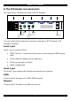
USER GUIDE 9. Pre-installation instructions Place cables away from fluorescent lights, air conditioners and other machines that are likely to generate electrical noise. Switch off the computer and disconnect the keyboard monitor and mouse. 10. Connecting the IP Extender to the host computer/KVM switch Connect the host computer / KVM switch to the IP Extender as follows: 1. Connect the connectors of one end of the 3 in 1 CPU cable to the Computer/Switch KVM ports of the IP Extender. 2.
SMART IP EXTENDER KVM switch STATION 2 SERIAL MOUSE POWER P110 KB PS/2 MOUSE SCREEN COMPUTER 5 COMPUTER 6 COMPUTER 1 COMPUTER 2 COMPUTER 7 COMPUTER 3 COMPUTER 8 COMPUTER 4 SD 3 in 1 CPU cable ProLiant DL360 9.1 - GB 10k ULTRA2 SCSI 9.1 - GB 10k ULTRA2 SCSI ProLiant DL360 85-265VAC 50/60 Hz COMPUTER / SWITCH SERIAL 1 www.minicom.com ISDN USER SERIAL 2 9.1 - GB 10k ULTRA2 SCSI 9.1 - GB 10k ULTRA2 SCSI ETHERNET POWER 9.1 - GB 10k ULTRA2 SCSI ProLiant DL360 Smart IP Extender 9.
USER GUIDE For further information about IMPI 1.5, see http://developer.intel.com/design/servers/ipmi/tools.htm To use the IPMI over a serial interface enable it in the host computer. This is done using BIOS settings or special utilities provided by the server manufacturer. Refer to the server manufacturer's manual site. Note! IPMI V1.5 is only supported by server systems manufactured in 2002 onwards. 13. Connecting the Internal Reset/Power Option Figure 8 shows the top view of the reset/power bracket.
SMART IP EXTENDER 8. Connect the bracket to the IP Extender Serial port 2 using the supplied SUB-D 9 to SUB-D 9 connector. 14. Connecting the External Reset/Power Option Refer to the of the External Power Switch Option guide to connect this to one of the serial ports. To date supported options are: • Avocent—SPC 1 800/1600 • Sentry In-Line Power Module 15.
USER GUIDE 19. Switching on After connecting IP Extender to the computer, switch on IP Extender first and then the computer. 20. Configuring the system The IP Extender's communication interfaces are based on TCP/IP, and it comes configured with the values listed below. • DHCP - active • IP address - 192.168.0.220 • Net mask - 255.255.255.0 • Default Gateway - None If the above values are unsuitable, change the IP configuration. This can be done in a number of ways: 21.
SMART IP EXTENDER 22. Configuration via local console There are two ways of doing this: (A) Connect the NULL modem cable to the computer and to IP Extender’s Serial 1 port. Use any Terminal software to connect to IP Extender. The screen shots below use Windows Hyperterminal. 1. Choose Start/Programs/Accessories/Communications/Hyperterminal. 2. When prompted enter a name and click OK. The Connect To box appears. See Figure 9. 3. Fill in the connection details.
USER GUIDE Figure 11 The Hyperterminal 6. Press Enter. Some device information and a prompt appear. 7. Type config and press Enter. Configuration questions appear. DHCP must be disabled. You can change the IP address, net mask and default gateway. Pressing Enter without entering values keeps the default values. To contact IP Extender from outside the LAN configure a gateway. To remove an already configured gateway, type 0.0.0.0.
SMART IP EXTENDER Host system mouse settings The host operating system has various settings for the mouse driver. IP Extender works with accelerated mice and is able to synchronize the host with the client mouse pointer. This is further discussed on page 24. The following may prevent proper mouse synchronization. Special vendor-specific Mouse drivers disrupt the synchronization process. Ensure these are not on the host system Windows XP has a setting ' enhanced pointer precision’. Deactivate it.
USER GUIDE This chapter deals with the HTTP interface. The other two interfaces are explained on pages 44 and 60. The Web browser must come with a Java Runtime Environment version 1.1 or higher. Without Java support, you can still maintain the remote host system using the administration forms displayed by the browser. We recommend the following browsers for an unsecured connection: • Microsoft Internet Explorer version 5.0 or higher with Windows 98, ME, 2000 and XP • Netscape Navigator 7.0 or Mozilla 1.
SMART IP EXTENDER Menu Work area Figure 13 The IP Extender Home page 27. Timeout After half an hour of non-activity the system automatically logs out. Clicking anywhere on the screen will lead back to the Login screen. 28. The Work area The Work area has a short summary about your IP Extender.
USER GUIDE Information bar Control buttons Computer buttons Figure 14 The remote console You can work on it with the keyboard and mouse. The delay with keyboard and mouse reactions - if any - depends on the line connection bandwidth. 30. Keyboard layout Your host keyboard changes its layout to match the remote host system. So for example if the host system uses a US English keyboard layout, special keys on a German keyboard won't work but will function as US English keys.
SMART IP EXTENDER In case IP Extender is connected to your local network environment and your connection to the Internet is available using a proxy server only without NAT being configured, the Remote Console is very unlikely to be able to establish the according connection. This is because today's Web proxies are not capable of relaying the RFB protocol. In case of problems, please consult your network administrator in order to provide an appropriate network environment.
USER GUIDE Mouse handling - The submenu for mouse handling offers two options for synchronizing the host and the client mouse pointer - explained on page 24. The option for 'Fast Sync' shows the hotkey if you defined one using the Remote Console Settings. Local cursor - Choose a cursor shape for the host mouse. The number of available shapes depends on the Java Virtual Machine, only version 1.2 or higher offers the full list.
SMART IP EXTENDER All messages are broadcast to ALL connected users. There is no option to direct a message to a particular user only. There is no message history, so messages can only be received after opening the Remote Console. 33. The Video settings From the Options menu choose Video Settings. The Video Settings box appears. See Figure 16. Figure 16 The Video settings The parameters have the following functions: Brightness - Brightness control. Contrast Red/Green/Blue- RGB contrast control.
USER GUIDE - Resets mode to factory defaults. - Resets all modes to factory defaults. - Saves changes. - Undoes changes that have not yet been saved. 34. Video Settings access In the User/Group Permissions section on page 38, it explains how to set access levels for all parameters including Video Settings access. A Remote Console user can always change Brightness, Contrast, Black level and picture positions, whatever his Video Settings access rights.
SMART IP EXTENDER 4. Active Desktop. Disable it. Or do not use a plain background, use a wallpaper. 37. Single mouse mode The information above applies to the Double Mouse Mode, where remote and host mouse pointers are visible and need to be synchronized. There is also the Single Mouse mode. In this mode only the client mouse pointer is visible. Single Mouse mode needs a Sun Java Virtual Machine 1.3 or later. Select the mode in the Remote console - see Figure 14.
USER GUIDE Automatic Detection - The encoding and the compression level is determined automatically from the available bandwidth and the current content of the video image. Normal - Best suited for many parallel users in a LAN environment. Compressed - For low bandwidth connections - Modem or ISDN. 1 is the lowest and 9 the highest compression rate. The IP Extender takes time to compress the data.
SMART IP EXTENDER Remote Console Button Keys - Button Keys simulate keystrokes on the remote system that cannot be generated locally. For example `Control + Alt + Delete' on Windows and DOS or `Control + Backspace' on Linux. Define a new Button Key as follows: Type the required keys e.g. Ctrl+Alt+Delete. The + sign means that the keys are pressed together. The – sign means the keys are pressed sequentially. The * sign inserts a pause with a definable duration. See page 32.
USER GUIDE several pre-settings (i.e. last day, last week) or an exact declaration of the start and the end date. Once you change the filter settings, click `Update' to update the shown entries. If the Get sensor names box is checked, all sensor IDs are shown with their respective names. The time shown in the log entries is the SEL time, meaning it is independent of the system time. The SEL time is shown at the top of the log table. Click Clear Event Log to delete all entries in the SEL repository. 42.
SMART IP EXTENDER External power If the external power option is enabled it will look like Figure 19. Figure 19 External power control The upper half is used to switch the power for the KVM port currently active. Use the KVM settings – see page 31 - to assign a port of the external power control to a KVM port. If no assignment exists, the option is disabled. The lower half offers controls for switching each port of the external power control directly.
USER GUIDE 43. Keyboard & Mouse Settings IP Extender supports different keyboard and mouse types. Click Keyboard & Mouse Settings. The settings appear as in Figure 20. Figure 20 Keyboard & Mouse Settings The elements of the Keyboard & Mouse Settings are explained below. Targeted KVM port 1. Choose the port to which a KVM switch is connected. 2. Press to display the current values for the selected KVM port. Without pressing alterations will NOT be made to the chosen port.
SMART IP EXTENDER Automatic speed detection When Mouse Acceleration on the local computer is enabled, check Automatic speed detection. We highly recommend disabling the Mouse Acceleration. G&D Equalizer – G&D Equalizer – This supports to the mouse synchronization for Guntermann & Drunck KVM switches. These switches perform an internal rescaling of the mouse movements, which cause the existing algorithm to break if IP Extender is connected behind such a switch.
USER GUIDE Active Port To switch to a computer: 1. Choose a number in the Active port Drop-down list. 2. Press . The computer screen appears in the Remote Console. Number of Ports To set the number of ports the KVM uses: 1. Choose a number in the Number of Ports Drop-down list. . The number of rows chosen appears in the KVM Port Settings 2. Press list. See Figure 22.
SMART IP EXTENDER Or choose your own hotkeys. The syntax to define a new hotkey is as follows: [ + | - | * ] . For example LShift-LShift-*1-Enter. A + sign means that the keys are pressed together. The – sign means the keys are pressed sequentially. Lshift means the left Shift key. The * sign inserts a pause with a definable duration. Add more than one pause if necessary. See Appendix B on page 16 for a list of key codes. 3. Press Apply at the bottom of the page. The settings are saved.
USER GUIDE 47. Enable local video port This option decides if the video output on the front panel of IP Extender is active and passing through the incoming signal from the host system. 48. Noise filter Define how IP Extender reacts to small changes in the video input signal. A large tolerance needs less network traffic and leads to a faster video display, but small changes in some display regions may not be recognized immediately.
SMART IP EXTENDER Figure 24 Custom Video Modes window Custom Modes Handling – switch custom modes off, or use in addition to the standard video resolutions, or use exclusively - Only. With Only you can force a special video mode for IP Extender. To change the parameters for a mode, choose the number and press Update. X Resolution - Visible number of horizontal pixels. Y Resolution - Visible number of vertical pixels. Horizontal Frequency (Hz) - Horizontal (line) frequency.
USER GUIDE The IP Extender is factory set with a supervisor user called `super' with the password ‘smart’. Change the super user password immediately after accessing the IP Extender. Figure 25 The User/Group Management settings 52. Existing user Select an existing user for modification or deletion. Once selected, click to see the user information. 53. New user name Enter a login name for a new user here. Ensure that it is not the same as a current user or group. 54.
SMART IP EXTENDER 59. New group name To create a new group, enter a new group name. 60. Create User button Once the required fields are filled in, click the Create User button to create a new user. 61. Delete User button To delete a user: 1. Select a user in the Existing users Drop-down list. 2. Click the Lookup button. The complete user information appears. 3. Click the Delete User button. Note: The factory set supervisor user `super' cannot be deleted, but it can be renamed. 62.
USER GUIDE 65. Create group button To create a group: 1. Type a name into the New group name box 2. Click the Create group button. 66. Delete Group button To delete a group: 1. Select a group in the Existing groups Drop-down list. 2. Click the Delete group button. 67. Modify Group To modify an existing group select the group in the Existing group control. The group's name field can be modified. Finally click the Modify group button. 68.
SMART IP EXTENDER Figure 26 User/Group Permissions Each user or group has a set of access rights to the IP Extender functions. The user 'super' always has unalterable full access rights. A newly created user has the access rights of all groups he belongs to. You can change the access rights in the User/Group Permissions panel. The panel shows the changes to the access rights inherited by the user's ancestors only.
USER GUIDE Using a function. allow access means you can use it. deny access means you cannot use it. Group setting – Use the access rights inherited from the group(s), the user belongs to. 3. Select the desired permission. 4. To add the right, click Add. To remove the right, check the Delete Entry box. 5. Click Apply. 70. Network Settings From the IP Extender Menu choose Network Settings. The Network Settings appear. See Figure 27.
SMART IP EXTENDER IP auto configuration Choose between the 3 options. None – no IP auto configuration. In this case type a static IP address in the appropriate settings below. DHCP - When selected, IP Extender will contact a DHCP (Dynamic Host Configuration Protocol) server in the local sub-net to obtain a valid IP address, gateway address and net mask. Before you connect IP Extender to your local subnet, complete the corresponding configuration of your DHCP server.
USER GUIDE Remote Console & HTTPS port Port number at which IP Extender's Remote Console server and HTTPS server are listening. If empty the default value is used. HTTP port Port number at which IP Extender's HTTP server is listening. If empty the default value is used. Telnet port Port number at which IP Extender's Telnet server is listening. If empty the default value is used. Bandwidth limitation The maximum network traffic generated through the IP Extender Ethernet device.
SMART IP EXTENDER IP Extender is reachable via the IP address of the DSL router, which is dynamically assigned by the provider. Since the administrator doesn't know the IP address assigned by the provider, IP Extender connects to a special dynamic DNS server in regular intervals and registers its IP address there. The administrator can contact this server as well and pick up the same IP address belonging to his card.
USER GUIDE Check interval - Interval for reporting again to the Dynamic DNS server by IP Extender. IP Extender has its own independent real time clock. Ensure the time setting is correct by configuring a timeserver see page 32. IP Extender registers itself to the Dynamic DNS server slightly different from the time configured. To reduce load peaks on the server we add a random time (0-10 min) to the absolute time value. 72.
SMART IP EXTENDER Layer-2 protocol - responsible for the error-free movement of data between network nodes. Choose between the High-level Data Link Control (HDLC) and X.75. You can leave this option untouched in case you use a standard network connection as built in Windows or Linux. Enable hang-up timer for incoming calls - Check to hang up an incoming connection. Hang-up timeout - For outgoing connections only where IP Extender is configured for callback.
USER GUIDE Callback connections only. Check Enable callback. Uncheck Force callback. Make an entry for every allowed client and check the call back after box. 73. Modem Settings IP Extender has the option of remote access using a telephone line. Connect the modem to IP Extender’s serial interface. Using a telephone line means building up a dedicated point to point connection from your console computer to the IP Extender.
SMART IP EXTENDER Figure 31 Serial Port Settings In the IP Extender Serial Settings specify the devices connected to the two Serial ports. Serial Port 1 The port options are listed below Configuration login –If this option is checked you can only use the port for the initial configuration and no other function. Modem - Connect a modem to Serial 1 port. See section 73 below Serial line speed - Most modems today will support the default value of 115200 bps. For older modems lower the speed.
USER GUIDE IPMI over Serial - Check to use this serial port for IPMI 1.5 over serial. See page 56 for more information. Passthrough… - Connect an arbitrary device to the serial port and access it (assuming it provides terminal support) via telnet. Select the appropriate options for the serial port and use the Telnet Console (see page 50) or a standard telnet client to connect to IP Extender. For more information, see page 60.
SMART IP EXTENDER Figure 33 Button Press Durations box External Power Option To configure the External Power Option connected to Serial port 2, click change external power switch option. SPC 800/1600 - Using the AvocentTM SPC, switch power for more than one system connected to IP Extender through a KVM switch. To use this device enter a username and password, which exist on the SPC and have the privileges to switch power for each port.
USER GUIDE 75. Security Settings From the IP Extender Menu choose Security Settings. The Security Settings appears. See Figure 34. Figure 34 Security Settings SSL settings Force HTTPS - Access the Web front-end only using an HTTPS connection. IP Extender won't listen on the HTTP port for incoming connections. Disable SSLv2 ciphers – disables SSLv2 ciphers. Only version 3 or higher is enabled.
SMART IP EXTENDER You can generate and install a new certificate unique to a particular card. IP Extender can generate a new cryptographic key and the associated Certificate Signing Request that needs to be certified by a certification authority (CA). A CA verifies you are who you claim to be and signs and issues a SSL certificate to you. To create and install a IP Extender SSL certificate: 1. From the Security Settings page choose Create your own SSL certificate. The window appears as in Figure 35.
USER GUIDE 4. Press Download CSR to download the CSR to your administration machine. 5. Send the CSR to a CA for certification. They will send a new certificate 6. Press Upload to upload the certificate to IP Extender. The certificate uploads. Important! If you destroy the CSR on IP Extender there is no way to get it back! If you deleted it, repeat the above steps. Telnet Settings Enable Telnet access - Access over Telnet client. For better security disable Telnet access.
SMART IP EXTENDER NOTE: The order of the rules is important. The rules are checked in ascending order until a rule matches. Rules below the matching one are ignored. The default policy applies if no match has been found. Append a rule - Enter the IP/Mask and set the policy. Then press . Insert a rule - Enter the rule number, IP/Mask and set the policy. Then press . Replace a rule - Enter the rule number, IP/Mask and set the policy. Then press . Delete a rule - Enter the rule number and press .
USER GUIDE 76.
SMART IP EXTENDER Figure 36 SNMP settings You can change the following parameters: Enable SNMP Agent - When checked, IP Extender will answer to SNMP requests. If a community is blank, you cannot perform the request. E.g. if you want to disable the possibility to reset IP Extender via SNMP, don't set a write community. Read Community - This is the SNMP community, which allows you to retrieve information via SNMP.
USER GUIDE Trap destinations Enter IP addresses, to which the traps will be sent. For every IP address, set an according community so that your management client can identify the SNMP traps. After making the entries click 77. . The IP Extender SNMP MIB Click the link to access the IP Extender SNMP MIB file. With it, an SNMP client can communicate with IP Extender. 78.
SMART IP EXTENDER IPMI over Serial - If your host system supports IPMI V1.5 and has an Intel EMP (Emergency Management Port, usually COM2) connector, you can connect IPMI through serial port 1 on IP Extender. Please note: • Set the EMP port to Always enable and switch off the Restricted Mode. • The BMC should accept a null username and a non-null password account as login. • Passwords are 4 -16 characters long.
USER GUIDE Type of external LDAP Server - Set the type of the external LDAP server. This is necessary since some server types require special handling. Also the default values for the LDAP schema are set appropriately. Choose between Generic LDAP Server, Novell Directory Service and Microsoft Active Directory. If you don’t have Novell Directory Service or Microsoft Active Directory then choose Generic LDAP Server and edit the LDAP schema used (see below).
SMART IP EXTENDER After a smooth upload the Update Firmware panel appears showing the current firmware version number and the uploaded firmware version number. 4. Press the Update button. The firmware updates. Warning! This process is irreversible; ensure the IP Extender's power supply won't be interrupted during the update process, as this may cause damage. 5. When prompted reset IP Extender manually by pressing the button. When pressed all connections to the administration or Remote console close.
USER GUIDE 84. Access via Telnet Connect via a standard Telnet client using IP Extender’s Telnet server. Use it for passthrough access to a device connected to serial port 1. Connect any serial device, which offers terminal access via its serial port and access it using the Telnet interface. Set the serial settings - see page 44 - according to the requirements of the device. Connect to IP Extender in the usual way required by the Telnet client, e.g. in a UNIX shell: telnet 192.168.0.
SMART IP EXTENDER Frequently Asked Questions Q 1: The client mouse doesn't work or is not synchronized. A: Ensure the IP Extender mouse settings match the mouse model. Also see page 24 Q 2: Bad video quality or grainy picture A: Use the brightness and contrast settings - see page 23. Use the auto adjustment feature to correct a flickering video. Q 3: Login fails. A: Was the correct user and password given? On delivery, the user "super" has the password "smart". Configure your browser to accept cookies.
USER GUIDE Glossary of terms ACPI - A specification that enables the operating system to implement power management and system configuration. ATX - Advanced Technology Extended: A particular specification of a motherboard introduced by Intel in 1995. BMC - Board Management Controller: implements the IPMI based main board management functions. DHCP - Dynamic Host Configuration Protocol: protocol for dynamically assigning IP configurations in local networks.
SMART IP EXTENDER Appendix A: IP Extender Video modes The IP Extender supports the following video modes. Do not use other custom video settings.
USER GUIDE Appendix B: Key codes Figure 40 illustrates the keys on a standard 104 key PC keyboard with a US English language mapping. These keys are used to define keystrokes or hotkeys for several IP Extender functions. The keys may not represent keys used on international keyboards. Most modifier keys and other alphanumeric keys are in identical positions, whichever language mapping you are using.
SMART IP EXTENDER Key Psc Scrl Brk Ins Pos1 Pup Del Pdn Key code PRINTSCREEN SCROLL_LOCK BREAK INSERT HOME PAGE_UP DELETE PAGE_DOWN UP LEFT DOWN RIGHT The numerical keypad codes Key Key code num NUM_LOCK 0 NUMPAD0 1 NUMPAD1 2 NUMPAD2 3 NUMPAD3 4 NUMPAD4 5 NUMPAD5 6 NUMPAD6 7 NUMPAD7 8 NUMPAD8 9 NUMPAD9 + NUMPADPLUS / NUMPAD/ * NUMPADMUL NUMPADMINUS CR NUMPADENTER 65 Alternative Alternative NUMPAD_PLUS NUMPAD_MUL NUMPAD_MINUS
USER GUIDE Appendix C: Pin assignments VGA HD-15 5 4 10 3 9 2 8 1 7 6 15 14 13 12 11 Pin 1 2 3 4 5 6 7 8 Assignment Red Green Blue Not connected GND GND red GND green GND blue Pin 9 10 11 12 13 14 15 Assignment 5V GND sync Not connected SDA, DCC, ...
SMART IP EXTENDER RJ 45 Connector ISDN 8 Pin 1 2 3 4 1 Assignment Not connected Not connected TX + RX + Pin 5 6 7 8 Assignment RX TX Not connected Not connected Serial SUB-D 9 Connector 1 1 2 6 Pin 1 2 3 4 5 3 7 4 8 5 9 Assignment DCD RX TX DTR GND Pin 6 7 8 9 Assignment DSR RTS CTS RI Serial SUB-D 9 Connector 2 1 2 6 Pin 1 2 3 4 5 3 7 4 8 Assignment DCD RX TX DTR, Reset1 GND 5 9 Pin 6 7 8 9 Pins 1 and 6 are bridged 67 Assignment DSR, Reset2 RTS, Power1 DTS, Power2 Not connected
USER GUIDE Appendix D: Technical specifications Host computer Operating systems Novel, Linux, Windows 98, ME, 2000, XP and later Client computer Operating systems Windows 98, ME, 2000, XP and later, Linux. Internet browser with full Java support Host computer resolution Up to 1280x1024 @75Hz Client computer resolution Recommended resolution should be higher than host computer resolution Host mouse driver Microsoft Driver or Operating System default mouse driver.
SMART IP EXTENDER 69
USER GUIDE 70