Phantom MX IP Installation Guide International HQ North American HQ European HQ Italy Jerusalem, Israel Linden, New Jersey Dübendorf, Switzerland Rome Tel: + 972 2 535 9666 minicom@minicom.com Tel: + 1 908 4862100 info.usa@minicom.com Tel: + 41 1 823 8000 info.europe@minicom.com Tel: + 39 06 8209 7902 info.italy@minicom.com www.minicom.com Customer support - support@minicom.com 5UM20109 V1.
PHANTOM MX IP Table of Contents 1. 2. 3. 4. 5. 6. 7. 8. 9. 10. 11. 12. 13. 14. 15. 16. 17. 18. 19. 20. 21. 22. 23. 24. 25. 26. 27. 28. 29. 30. 31. 32. 33. Welcome .........................................................................................................................................2 Introduction ....................................................................................................................................3 The MX IP system components .................................
INSTALLATION GUIDE 1. Welcome The Phantom MX IP system is produced by Minicom Advanced Systems Limited. Technical precautions This equipment generates radio frequency energy and if not installed in accordance with the manufacturer’s instructions, may cause radio frequency interference. This equipment complies with Part 15, Subpart J of the FCC rules for a Class A computing device.
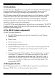
PHANTOM MX IP 2. Introduction The MX IP system from Minicom is a CAT5 based Distributed KVM Switching system with remote KVM access via IP. You can remotely access up to 63 computers. The system can be managed and controlled by 1 or 2 users. MX IP features remote KVM access and control via a LAN, Internet, or ISDN connection. MX IP provides a non-intrusive solution for remote access and control.
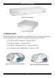
INSTALLATION GUIDE Figure 1 Phantom MX IP Figure 2 Phantom UPM 5. Remote units The Remote units are external boxes called Specters. Each remote computer has a Specter connected to it.
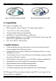
PHANTOM MX IP Figure 5 The Phantom Specter II RS232 Figure 6 The Phantom Specter II USB 6. Compatibility The system is compatible with: • • • • • • IBM compatible, Silicon Graphics, SUN and Alpha computers VGA, SVGA, or XGA video standards All major computer and server manufacturers IntelliMouse™, Logitech WheelMouse, and PS/2 mice Microsoft DOS, Windows 3.1, 95, 98, 2000, NT4, ME and XP. Novel, Linux, SGI, BeOS, HP UX, Alpha UNIX, Open VMS PS/2, SUN, RS232, USB interfaces 7.
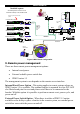
INSTALLATION GUIDE MX IP automatically detects the current video mode of the console, however manual tuning is recommended to get the best video quality. MX IP will accept video streams up to 110 MHz dot clock. This results in a screen resolution of 1280x1024 dots with a refresh rate of 75 Hz. 8. System configuration Figure 7 illustrates the MX IP usage scenario Figure 8 illustrates the basic configuration of MX IP, showing it connected to a computer rack, the UPM, and to the IP network.
PHANTOM MX IP The MX IP system A Dual-Management Server Solution over IP 2nd Administrator USER POWER 1 To first Specter’s System In port SUN Specter 2 3 in 1 CPU cable LI NK AC TIVE MINICOM PHANTOM Specter LIN K A CTI VE MINICOM Total CAT5 cable length in the system - up to 110m / 360ft MX IP UNIX Terminal Server SERIAL 3 3 2nd USER OUT SYSTEM IN SERIAL 2 SERVICE SERIAL 1 USER ETHERNET LI NK AC TIVE MINICOM Shielded CAT5 FTP cables USB Specter PHANSpecter TOM 63 COMPUTER R
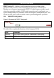
INSTALLATION GUIDE IPMI Version 1.5 - defines a serial connection to access certain system parameters and perform system actions like powering down or a hard reset. Modern server systems, supporting the IPMI V1.5 specification, provide a mode where the externally available COM2 serial connection can be configured as a system management port (sometimes called an emergency management port). MX IP may use this port in order to enable remote system management operations. 10.
PHANTOM MX IP 11. The MX IP rear panel ports The figure below illustrates the ports on the MX IP.
INSTALLATION GUIDE 12. • • • Pre-installation instructions Switch off all computers, and disconnect the power cords Place cables away from fluorescent lights, air conditioners, and machines that are likely to generate electrical noise Ensure that the total cable length does not exceed 110m / 360ft 13. The MX IP system cables The MX IP package contains the following cables. 3 in 1 CPU cable Null Modem cable CAT5 FTP cables RS232 Serial cable 14.
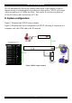
PHANTOM MX IP 4. You can connect a local KVM console to the User ports of the MX IP and work locally on the Phantom system. Figure 11 illustrates the connections. Optional local computer To computer's Mouse port USER POWER COMPUTER www.minicom.
INSTALLATION GUIDE 16. Connecting the MX IP system The MX IP system is connected using Shielded CAT5 FTP System cable. The Shielded CAT5 FTP System cable consists of a Shielded CAT5 FTP (Foil Shielded Twisted Pair) Solid Wire 2x4x24 AWG (America Wire Gauge) cable terminated with RJ-45M connectors. The total length of the CAT5 cables in the system can be up to 110m/360ft, see the configuration diagram on page 7. This includes the CAT5 loop and the cable distance from the MX IP to the UPM. Recommendation.
PHANTOM MX IP Phantom Specter IN OUT SYSTEM OUT SYSTEM IN Figure 12 The Phantom Specter ports 19. Connecting the Specter II PS/2 Connect the Specter as illustrated in the figure below. Connect the Specter to a computer with the built-in cables. Connect the Specter to the Phantom system using Shielded CAT5 FTP cables. The Phantom Specter draws its power via the computer’s Keyboard port.
INSTALLATION GUIDE 21. The RS232 power options 1. USB connection for power only – see Figure 14. To USB Port (for power only) To RS232 Port To System IN port of next To System Out port unit Shielded CAT5 FTP System cables To System Out port of previous unit To System In port Figure 14 The Specter RS232 connections 2.Server without USB - connect a USB to PS/2 Adapter – illustrated below. Connect the adapter to the Keyboard port. Figure 15 The USB to PS/2 Adapter 3.
PHANTOM MX IP 23. Connecting the Specter USB Connect the Specter as illustrated in the figure below. Connect the Specter to a computer with the built-in cables. Connect the Specter to the Phantom system using Shielded CAT5 FTP cables. The Phantom Specter draws its power via the computer’s USB port. To Video Card To USB Port To System IN port of next To System Out port unit Shielded CAT5 FTP System cables To System Out port of previous unit To System IN port Figure 17 The Specter USB connections 24.
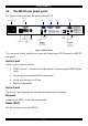
INSTALLATION GUIDE 25. Controlling the RS232 Specters You can control the RS232 Specters from the Telnet window of the Phantom MX IP when the system is connected over the Ethernet. Connect the Null Modem cable to the MX IP as illustrated in the figure below. P110 SD Null Modem cable SERIAL 3 COMPUTER SERIAL 2 MX IP SERIAL 1 USER RST POWER 26.
PHANTOM MX IP RS232 Terminal P110 SD Login: admin Password_| d i g i t a l VT420 Contrast Bright MX IP SERIAL 3 COMPUTER SERIAL 2 SERIAL 1 USER RST POWER 2nd USER OUT SYSTEM IN SERVICE ETHERNET Figure 18 The RS232 terminal connected to the MX IP 27. Connecting the IPMI option IPMI Version 1.5 defines a serial connection to access certain system parameters and to perform actions like switching off the system or performing a hard reset.
INSTALLATION GUIDE Note! IPMI V1.5 is only supported by server systems manufactured in 2002 onwards. 28. Connecting the Internal Reset/Power Option Figure 19 shows the top view of the reset/power bracket. To Reset pin on Mainboard To front panel Reset switch To Power On pin on Mainboard To front panel Power switch Figure 19 Reset/power bracket Additional cables are required to enable the remote reset and power functions. To install the bracket: 1.
PHANTOM MX IP 29. Connecting the External Reset/Power Option Refer to the of the External Power Switch Option guide to connect this to one of the serial ports. To date supported options are: • SPC 800/1600 • Sentry In-Line Power Module • Intelligent Power Module • Leunig ePowerSwitch • Leunig ePowerSwitch –M/S 30. Connecting to Ethernet The Ethernet connector on the MX IP can be used either for a 100 Mbps 100BASE-TX connection or for a 10 Mbps 10BASE-T connection.
INSTALLATION GUIDE 33. Connecting the RS232 Serial cable To operate the Phantom system with the Control software located on the Marketing & Documentation CD, connect the RS232 Serial cable. To connect the RS232 Serial cable: 1. Connect the cable’s RJ11 connector to the MX IP’s Service connector. See Appendix A for the Service Connector Pin-out. 2. Connect the cable’s DB9F connector to a Serial port on the computer’s rear panel. The figure below illustrates the connections.
PHANTOM MX IP Appendix A: Pin assignments RJ 45 Connector Ethernet 8 Pin 1 2 3 4 1 Assignment TX + TX RX + Not connected Pin 5 6 7 8 Assignment Not connected RX Not connected Not connected Serial SUB-D 9 Connector 1 1 2 6 Pin 1 2 3 4 5 3 7 4 8 5 9 Assignment DCD RX TX DTR GND Pin 6 7 8 9 Assignment DSR RTS CTS RI Serial SUB-D 9 Connector 2 1 2 6 Pin 1 2 3 4 5 3 7 4 8 Assignment DCD RX TX DTR, Reset1 GND 5 9 Pin 6 7 8 9 Pins 1 and 6 are bridged 21 Assignment DSR, Reset2 RTS, Power1
INSTALLATION GUIDE RS232 Serial cable pin-out RJ11 Service 1 2 3 4 5 6 Signal N/C TXD RXD N/C GND N/C Serial SUB-D 9 Connector 3 Pin 1 2 3 4 5 6 7 8 9 Signal N/C RXD TXD DTR GND DSR RTS CTS N/C 22 DB9 2 3 5 -
PHANTOM MX IP Appendix B: Technical specifications Host computer Operating systems DOS, Novel, Linux, UNIX, Windows 3.1,9X, ME, NT4, 2000, XP, 2003 Server and later Client computer Operating systems Windows 98, ME, 2000, XP and later, Linux, MAC and SUN.
INSTALLATION GUIDE Operating temperature 5°C to 40°C / 41° to 104°F Storage temperature -40°C to 70°C / -40° to 158°F Operating humidity 10% to 90% (non-condensing) Storage humidity 5% to 95% (non-condensing) Warranty 3 years 24
PHANTOM MX IP 25