
Installation guide
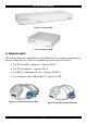

PHANTOM MX IP
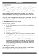
3 in 1 CPU
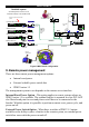
cable
To last Specter’s
System Out port
Shielded CAT5
FTP cables
To first Specter’s
System In port
www.minicom.com
USER COMPUTER
SERVICEPOWER
85-265VAC 50/60 Hz
To System port
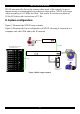
UPM
MX IP
SD
P110
ProLiant DL360 1U Server
SUN Ultra 1U Server
UNIX Terminal Server
RS232 Specter
1
2
PHAN
63
3
Windows 2000 Server
IP Network
Remote
Administrator
2
nd
Administrator
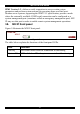
Connect up to 63 servers in the
system
The MX IP system
A Dual-Management Server Solution over IP
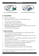
Mixed Platform Example - PS/2, SUN, RS232, USB
USB Specter
SUN Specter
PS/2 Specter
Total CAT5
cable length
in the
system - up
to 110m /
360ft
www.minicom.com
POWER
85-265V AC 50/
60 Hz
COMPUTER
SYSTEM
2nd
USER
OUT
IN
SERVICE
RST
SERIAL 3
ETHERNET
USER
SERIAL 1SERIAL 2
LINK
ACTIVE
MINICOM
Specter
PHANTOM
LINK
ACTIVE
MINICOM
Specter
PHANTOM
LINK
ACTIVE
MINICOM
Specter
TOM
LINK
ACTIVE
MINICOM
Specter
PHANTOM
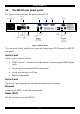
Figure 8 MX IP basic configuration
9. Remote power management
There are three remote power management options:
• Internal reset/power
• External scalable power switch box
• IPMI Version 1.5
The management system to use depends on the remote server interface.
Internal Reset/Power Option - This option applies to remote systems where no
IPMI Version 1.5 is available. The optional bracket is mounted in a free PCI/AGP
slot. Main board pins for reset and power on/off have to be connected to the
bracket. With this option it is possible to perform a remote reset, power cycle, and
power on/off.
External Power Switch Option - When there is neither a IPMI V1.5 option
available or the ability to place a bracket in the remote system, an external power
switch box can switch the power on and off.
7