
User manual

miniDSP Ltd – Hong Kong / Email : info@minidsp.com / Features and Specifications are subject to change without prior notice
P 10
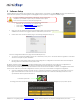
4.1.2 Preset Memory selection
The miniDSP 4x10 Hd allows the user to create up to 4 preset memories for a quick reconfiguration of the processor. Under each
configuration, all settings of the platform are saved.
Placed at the top of the user interface, the use of configurations couldn’t be easier. Simply toggle between configurations by clicking
on the config button. The currently selected configuration
WARNING: By toggling configurations, you may go from a working configuration (i.e. correct volume/setup/Eq) to an unknown
(or improperly configured) configuration. We therefore recommend that you perform a quick configuration offline (without
being connected/synchronized to the processor) to prevent any damage to your equipment.
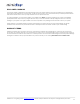
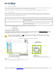
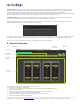
4.1.3 Input Tab
The first step in configuring your MiniDSP consists in making sure audio is being fed to the input correctly. To do so, click on the button
labeled “inputs”. The RMS meter will quickly indicate the average value of the input signal in dBFS (i.e. relative to the full scale of the
ADC or 24bit I2S signal). Individual faders control the digital gain at the input and per channel mute status.
This meter displays dB full scale (dBFS) values and will saturate at 0dBFS (full scale of the ADC). Do make sure to keep the signal below
0dBFS (red color) and with enough headroom (say 10dB) to prevent saturation during the typical audio peaks of a music source.
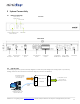
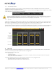
4.2 Matrix Tab
The matrix DSP object is the DSP object linking inputs to outputs. While very typical on commercial DSP products, it may be new for
some of you. The following section will summarize the basics of configuration.
Matrix switchers work as a “matrix” where:
- Rows are inputs
- Columns are outputs
- And the status(ON/OFF) of the buttons at the crosspoint of rows (inputs) & columns (outputs) will define the routing and
mixing of the audio to one of 8 outputs. .
The following configuration shows how the matrix should be configured for a 4way configuration with:
- Left analog audio input being routed to analog outputs 1-4
- Right analog audio input being routed to analog outputs 5-8
Per channel
mute button
Per channel
Level control
Per channel
monitoring
Per channel
PEQ
button
Custom
Label