DDRC-88A 8-CHANNEL AUDIO PROCESSOR WITH DIRAC LIVE® TECHNOLOGY User Manual mi niDSP Ltd, Hong Kong / www.minidsp.
Revision history Revision 0.1 0.2 0.3 0.4 1.0 1.1 Description First draft Preliminary pre-release version Draft pre-release for comment Second draft pre-release for comment First public release Updated firmware update procedure Date 25 November 2014 5 December 2014 20 January 2015 28 January 2015 2 February 2015 20 May 2015 mi niDSP Ltd, Hong Kong / www.minidsp.
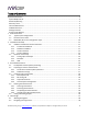
T ABLE OF C ONTENTS Important Information....................................................................................................................................5 System Requirements..................................................................................................................................5 Disclaimer/Warning ....................................................................................................................................5 Warranty Terms...................
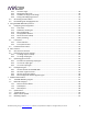
.2.1 The Auto Target...................................................................................................................... 30 4.2.2 Editing the target curve........................................................................................................... 30 4.2.3 Guidelines for target curve design ........................................................................................... 31 4.2.4 Saving and loading target curves .....................................................
I MPORTANT I NFORMATION Please read the following information before use. In case of any questions, please contact miniDSP via the support portal at minidsp.desk.com. S YSTEM REQUIREMENTS To configure your DDRC-88A audio processor, you will require a Windows PC with the following minimum specification: Intel Pentium III or later, AMD Athlon XP or later 2 Gigabytes (GB) of RAM or higher Keyboard and mouse or compatible pointing device Microsoft• ® Windows® Vista® SP1/Win7/Win8 Microsoft• ® .
Warning: This equipment has been tested and found to comply with the limits for a Class B digital device, pursuant to Part 15 of the FCC Rules. These limits are designed to provide reasonable protection. This equipment generates, uses and can radiate radio frequency energy and, if not installed and used in accordance with the instructions, may cause interference to radio communications. However, there is no guarantee that interference will not occur in a particular installation.
1 P RODUCT O VERVIEW Thank you for purchasing a miniDSP DDRC-88A audio processor powered by Dirac Live®, the world’s premier room correction solution. We are delighted to offer you this software and hardware combination, the fruit of extensive research and development and years of experience in sound system tuning. The DDRC-88A is an 8-channel digital audio signal processor (DSP) running the Dirac Live® room correction algorithm.
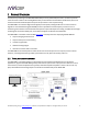
In studio or sound reinforcement applications, the DDRC-88A is typically connected between a mixing console and power amplification, as shown below. Individual channels can be set for either full-range or subwoofer operation. Computer connectivity is used to perform acoustic measurements and generate digital room correction filters. Up to four sets of correction filters can be stored on the DDRC-88A processor and recalled from the front panel or via an infrared remote.
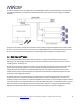
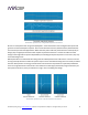
Illustration of Dirac Live® magnitude response correction Dirac Live® accomplishes this using mixed-phase filters – filters that match a desired magnitude response and generate a customized impulse response. This contrasts with the minimum-phase and linear-phase filters that are commonly used in audio applications.
1.3 DDRC-88A / DIRAC LIVE® CONFIGURATION STEPS The steps for configuring the DDRC-88A audio processor with Dirac Live® are summarized as follows: 1. Connect the DDRC-88A audio processor into your system and install software. See Section 2, Installation and Setup. 2. Run a series of acoustic measurements using the Dirac Live Calibration Tool For miniDSP program, to capture the acoustic behavior of your speakers and room. See Section 3, Acoustic Measurement. 3.
2 I NSTALLATION AND S ETUP 2.1 S OFTWARE INSTALLATION AND LICENSE ACTIVATION Please read and follow all steps in this section carefully. If you run into difficulties during installation and license activation, please contact miniDSP support via minidsp.desk.com. 2.1.1 Framework installation Prior to installing the software, download and install the following frameworks. You will need to accept the license agreements in order to successfully complete the installation.
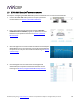
2.1.3 License activation 1. If you are running the Dirac Live Calibration Tool already, quit from that program. (You cannot run this program and the DDRC-88 Utility program at the same time.) 2. Start the DDRC-88 Utility program. It will appear as shown on the left below. 3. Connect your DDRC-88A processor to your computer via USB, then click on the Connect button. It will change to a green tick. 4. Click on Get Activation Serial Number.
Notes: 1. The serial number that must be entered in the activation screen is not the serial number printed on the hardware unit. A unique activation serial number for Dirac Live is programmed into the firmware of each unit and can only be accessed with the DDRC-88 Utility program (step 4 above). 2. The email address used during license activation is not related to your user account on miniDSP.com.
2.2 H ARDWARE CONNECTIVITY All connections to the DDRC-88A are made on the rear panel. 2.2.1 Analog input and output Up to eight channels can be connected to the DDRC-88A. Be sure to take careful note of the channel numbering: On the input side, it is very strongly recommended that all connections be of the same type – i.e. balanced or unbalanced.
2.2.2 DC Power Fit the supplied IEC cable to the 12 VDC power supply. Plug the AC mains plug into the power outlet, and then plus the DC connector into the +12VDC socket on the rear panel of the DDRC-88A. Apply power to the DDRC-88A only after all analog input and output connections have been made. The DDRC-88A uses little power and can be left powered on.
3 A COUSTIC MEASUREMENT The Dirac Live Calibration Tool For miniDSP uses a set of measurements made in your listening room to gather all the acoustical information about your room and speakers that it needs to calculate the correction filters. The measurements are made using the DDRC-88A processor and a miniDSP UMIK-1 measurement microphone (must be purchased separately). 3.
3.2 P REPARING FOR ACOUSTIC MEASUREMENT 3.2.1 Connections and microphone placement The figure below shows a typical connection diagram for performing acoustic measurement. No changes to the audio connections are needed. Simply: 1. Connect the supplied USB (type A to type B) cable from the DDRC-88A to a USB port on the computer. 2. Connect a USB cable (type A to mini type B) from the UMIK-1 to a USB port on the computer.
3.3 C ONFIGURING FOR MEASUREMENT Start Dirac Live Calibration Tool For miniDSP (DLCT). Be sure to quit the DDRC-88 Utility program before starting Dirac Live Calibration Tool for miniDSP. Running the two programs at the same time will result in communication conflicts and odd behavior. Logo and status progress bar This area shows a progress bar with current status when the program is performing calculations. If the program seems unresponsive at any time, check the status here.
3.3.1 Sound System tab On the Sound System tab, set the following parameters. Choose system configuration Use the dropdown menu to select your system configuration. For multi-channel surround-sound, use 5.1 Speaker System or 7.1 Speaker System if it is desired that Dirac Live calibrate for a 10 dB “LFE alignment gain” to the subwoofer channel.
3.3.2 Mic Config tab On the Mic Config tab, set the following parameters. Recording device Preset to the UMIK-1. If the UMIK-1 is not showing, ensure that the UMIK-1 is connected securely to the computer via USB, then go back to the Sound System tab and click on Rescan. Then use the drop-down menu to select the “Microphone” item underneath “UMIK-1”. Recording channel Select 1 from the drop-down menu.
3.3.3 Output & Levels tab On the Output & Levels tab, set Output volume quite low. If you have another volume control “down-stream” of the DDRC-88A, set it about halfway and increase it later if needed. Click on the Test button for the left channel and gradually increase the output volume until it is at a moderate level, such that your voice would have to be raised to converse with someone sitting next to you .
3.3.4 Custom System configuration On the Sound System tab, choose the Custom System configuration if any of the following apply: Your system does not fit any of the three predefined configurations (Stereo, 5.1, 7.1). You want to use a different channel mapping than the default. You do not want the DDRC-88A to calibrate for a 10 dB LFE alignment gain on the subwoofer channel. After choosing Custom System, you will need to select the number of channels that you want to use.
3.4 R UNNING THE MEASUREMENTS Acoustic measurements are performed on the Measurements tab. Measurements should be performed under good conditions if possible. While the measurement technique used by Dirac Live is quite robust, low-frequency noise (traffic, machinery, aircraft, storms) in particular can adversely affect measurement accuracy. A high level of ambient noise can degrade signal to noise ratio and prevent the algorithm from analyzing the test sweep signal properly.
3.4.1 Listening environment The Measurements tab presents three different listening environments as a visual guide to positioning the microphone for each of the nine measurements: Chair, for a single listening seat; Sofa, for multiple listening seats; and Auditorium, for a large dedicated home theater or larger venue with staggered seating. Use the icons at the left of the screen to select the listening environment.
For example, if using the Chair listening environment, spread the microphone positions over a circle with a diameter of a meter (three feet). Vary the height of the microphone up and down by 30 cm (one foot) from the initial position. If using the Sofa or Auditorium listening environment, again spread the measurement locations over the full listening area and vary microphone height by a significant amount.
3.4.3 Completing the measurements After each successful measurement, the location marker (red arrow) will advance to the next location. Move the microphone to that location, using the three views (top, front, oblique) as a guide to positioning it. Then click on Start again. Repeat this process until all nine locations have been successfully measured. Note: it is good practice to save the project periodically while performing measurements (see Saving and loading projects below). 3.4.
4 F ILTER D ESIGN The Filter Design tab shows sets of graphs for the various channels. Click on the tabs at the right to display the response graphs for different sets of channels (left and right, center, subwoofer, and surrounds, in the case of 5.1 and 7.1 systems). For each set of graphs, a number of variants can individually be turned on and off with the checkboxes above the graphs. Avg. spectrum (before) The average of the measured magnitude responses. These plots are shown in light blue. Avg.
The graphs showing all nine measurements are useful for seeing how much variation there is across the listening area: To display the impulse response instead of the magnitude response, click on the Impulse button at the top left of the display. All nine individual impulse responses can be shown as well as the average response. The predicted responses after correction can be viewed after filters are generated with the Optimize button (see Generating correction filters below).
To unlink a channel, click on its chain icon. It will then be unlinked from the other channels. To link it to another channel or groups of channels, drag its tab on top of the channel or group of channels that you want it linked to. Initially, you may wish to link all speaker channels together, as shown at right in the diagram above, as this will make it easier to experiment with target curves.
4.2 D ESIGNING YOUR TARGET CURVE The target curve is the desired in-room magnitude response with the DDRC-88A processor performing digital room correction. 4.2.1 The Auto Target When first viewing the Filter Design tab, an estimated target curve suitable for your speakers is shown as the red curve. This calculated target curve can be restored at any time by clicking on the Auto Target button. Note: restoring the auto target will erase the current target curve.
To alter the region of correction, drag the grey handles on either side of the graph. Note that you can’t drag these handles over an anchor point, so you may need to move or delete an anchor point that is “in the way.” If channels are linked, the same target curve is used for that group of linked channels. To create a separate target curve for a single channel, unlink it as described above in Working with graphs. 4.2.
High-frequency “tilt” The target curve is the desired measured response of loudspeakers in a room, In contrast to measurements made of a loudspeaker during its design under anechoic (measured in free space) conditions.
4.3 G ENERATING CORRECTION FILTERS Once you have a target curve set to your satisfaction, click on the Optimize button. The status bar will update as the algorithm progresses. The entire algorithm may take some time to complete, depending on the speed of your computer. When the algorithm completes, the predicted average magnitude response will be shown in green. (The predicted impulse response can be viewed by clicking on the Impulse button.
4.4 D OWNLOADING AND MANAGING FILTER SETS The Export tab initially shows four empty “slots” for filter sets (a filter set is one filter for every channel). Filter sets are managed with a “drag and drop” metaphor: To load the most recently generated filter set into the processor, drag the box at the top left (labeled “HT 15 Aug 2105” in the example) and drop it onto an empty slot.
5 USING THE DDRC-88A AUDIO PROCESSOR Once the desired correction filters have been downloaded into the DDRC-88A audio processor, the computer is not required and can be disconnected. 5.1 C ONFIGURING SOURCE EQUIPMENT Because of the effect of the Dirac Live algorithm, the settings required in source equipment may differ to the settings used prior to deploying the DDRC-88A. 5.1.1 Level trims Dirac Live aligns the gain of all channels.
subjective effect. We therefore recommend that target curves be used to tailor the sound on all channels to your liking first, and only then apply EQ in the source equipment if there is a need for rapid “on the fly” subjective EQ adjustments. 5.1.6 Other processing Any other processing can be applied in the same manner as you did prior to deploying the DDRC-88A in your system. In a home theater context, this includes down-mixing (for example from 7.1 to 5.
5.3 I NFRARED REMOTE CONTROL Many standard and programmable remote control units can be used with the DDRC-88A processor. Instead of adding another remote to your collection, the processor can “learn” the control codes of your current infrared (IR) remote if it supports one of the following remote control codes: NEC Sony Philips RC6 Apple Remote Learning is done with the DDRC-88 Utility program. After starting the program, click on the Connect button.
6 G AIN STRUCTURE When deploying a DSP solution in your audio system, a topic that becomes more important than with analog equipment is gain structure. This means that the signal levels throughout the system should be set high enough to maximize digital resolution and minimize noise, but not so high as to result in clipping and distortion. The DDRC-88A provides a great deal of flexibility in matching with other equipment.
6.2 C HOOSING GAIN STRUCTURE SETTINGS The input sensitivity is the voltage that generates a full-scale digital input signal to the DDRC-88A’s DSP (digital signal processor). The output gain setting specifies the voltage that results from a full-scale digital output signal from the DSP. The best choice of input sensitivity and output gain settings can be determined in two ways: by the output level of the source and the input sensitivity of the amplifier, or by the resulting input-output gain of the DDRC-88A.
Figure 6.2. Gain structure settings based on input and output levels Unbalanced output Balanced output Setting 0.9V 2V 4V 8V 0.9V 0 dB 6 dB 12 dB 18 dB 2V −6 dB 0 dB 6 dB 12 dB 8V −18 dB −12 dB −6 dB 0 dB Unbalanced input Balanced input Gain values are simplified to give exact multiples of 6dB. Figure 6.3. Input-output gain determined by connection type and gain structure settings mi niDSP Ltd, Hong Kong / www.minidsp.
6.2.1 To change input sensitivity Input sensitivity can be changed for unbalanced connection only, by moving a set of three jumpers on each channel. The diagram below illustrates the location of the jumper headers for each channel. For each channel that is to be changed, lift the jumpers and replace them in either the OPEN position (jumper pushed onto one pin only) or CLOSED position (jumper pushed onto both pins).
6.3 O PTIMIZING GAIN STRUCTURE If the acoustic output level of different channels shows substantial differences (greater than 6 dB), then there may be room to improve the gain structure of your system. Follow the procedure below carefully. Note that: You must not adjust the Channel volume sliders away from the maximum at any point in this procedure. It is not necessary to get all test meter readings at exactly the target level.
6.3.2 To increase output gain Before After Gain change (approx.) DIP switch DOWN Dip switch UP +6 dB Unbalanced connection Balanced connection (*4) +12 dB (*5) Unbalanced connection Balanced to unbalanced adapter (*6) +6 dB *4. This change can be made only if your amplifier has balanced inputs. *5. This gain change applies in the typical case in which the amplifier has the same sensitivity/gain on both balanced and unbalanced input connections.
6.4 LFE ALIGNMENT GAIN “Known as the LFE channel (for Low Frequency Effects), it handles bass created specifically for subwoofer boom effects and may also carry low frequency information from the other channels in order to enrich the overall soundtrack.” 5.1-Channel Production Guidelines, Dolby Laboratories Inc. “The LFE channel is recorded with a level offset of −10 dB.
If, on the other hand, the DDRC-88A is to be “aware” of the need for LFE alignment gain, then choose the 5.1 Speaker System or 7.1 Speaker System configuration. In this case, Dirac Live will calibrate for 10 dB higher acoustic output on the subwoofer channel by adjusting its internal trim on the subwoofer channel. This does not necessarily mean that the DDRC-88A will apply 10 dB of gain to its subwoofer channel – that is determined by the calibration process. 6.4.
6.4.3 LFE gain structure problems The difference in signal levels noted above for Custom Configuration is likely not a problem in practice, in most systems. If, however, you do experience issues with distortion on the subwoofer channel at high playback levels, it may be that you are clipping the subwoofer output of the source equipment or the subwoofer input of the DDRC-88A.
7 A DDITIONAL I NFORMATION 7.1 T HE DDRC-88 UTILITY PROGRAM The DDRC-88 Utility program is an auxiliary program for configuring certain functions of the DDRC-88A. It is not used for measurement or calibration. Master volume Displays the current master volume setting. Mute Mutes all audio output. Connect/Connected Click on the Connect icon to connect to the DDRC88A. To disconnect, quit from the DDRC-88 Utility. Get Activation Serial Number Click to get the unique activation serial number for this unit.
7.2 B ALANCED WIRING TIPS 7.2.1 Phoenix terminal blocks To make balanced connections, remove the terminal blocks from the rear of the DDRC-88A. Connect individual wires from a shielded pair cable to each set of screw terminals as shown below. After all connections to the terminal block are secure, firmly re-insert the terminal blocks. 7.2.2 XLR adapters If connecting the DDRC-88A to equipment that uses XLR connectors, suitable cabling can be made by cutting XLR-XLR or microphone cables in two.
7.3 S PECIFICATIONS Computer connectivity Driverless USB 2.0 control interface for Windows and Mac OS X Analog inputs 8 x Balanced (Terminal Block) or 8 x Unbalanced (RCA) inputs Analog outputs Maximum balanced input voltage: 8 VRMS Maximum unbalanced input voltage: 2.0 or 0.9 VRMS (jumper selectable) 8 x Balanced (Terminal Block) and 8 Unbalanced (RCA) outputs Maximum balanced output voltage: 8.0 or 4.0 VRMS (DIP switch selectable) Maximum unbalanced output voltage: 2.0 or 0.
7.4 T ROUBLESHOOTING The following table lists the most common causes of issues with the DDRC-88A. If following this table does not provide a solution, see Obtaining Support below. Item# Symptoms Troubleshooting recommendation 1 Cannot install software a. Confirm that you downloaded and installed the required frameworks first (see Software Installation). 2 The DDRC-88 Utility cannot connect to the DDRC-88A hardware unit a.
8 Unable to generate correction filters (Optimize button) a. Check that your computer is connected to the Internet and able to pass HTTP (web) traffic. b. Check that you do not have any other program running that is attempting to communicate with the DDRC-88A, such as the DDRC-88 Utility program. 9 No audio playthrough a. Check that the DDRC-88A processor is not muted. b. Check that the DDRC-88A processor master volume control is not turned down. c. Check that all cables are securely seated. d.
4. Click on the Open Hex File button and select the .hex file included in the download. It will have a name like ENC_DDRC88_Ver2.17_SS.hex. 5. Click on the Program/Verify button. The status bar will indicate progress. Do not disconnect the DDRC-88A during the firmware upgrade! 6. Click on the Reset Device button. The processor will return to normal operating mode, and can be used as normal. DO NOT DISCONNECT THE USB CABLE OR POWER FROM THE DDRC-88A WHILE FIRMWARE UPDATE IS IN PROGRESS.