
User manual

miniDSP Ltd, Hong Kong / www.minidsp.com / Features and speci fications subject to change wi thout pri or noti ce 17
3.2 PREPARING FOR ACOUSTIC MEASUREMENT
3.2.1 Connections and microphone placement
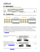
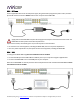
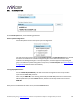
The figure below shows a typical connection diagram for performing acoustic measurement. No changes to the
audio connections are needed. Simply:
1. Connect the supplied USB (type A to type B) cable from the DDRC-88A to a USB port on the computer.
2. Connect a USB cable (type A to mini type B) from the UMIK-1 to a USB port on the computer.
Place the UMIK-1 microphone into a microphone stand and position the computer and cabling so that there is
enough freedom of movement to move the microphone into the needed locations. A small tripod stand is
supplied with the UMIK-1, but a larger stand with boom arm can be used if desired. If necessary a USB extension
(up to a total USB cable length of 5 meters) can be used. In larger spaces, an active USB repeater may be
needed. We recommend that the microphone be oriented vertically (pointed at the floor or ceiling) and the “90
degree” calibration file used (see Mic Config tab below).
3.2.2 Subwoofer settings
We recommend that the low pass filter of the subwoofer be disabled if possible, or set to its highest frequency if
it cannot be disabled. Any EQ on the subwoofer should be disabled or set “flat.” High pass filters used to protect
the driver from over-excursion should be left in place.
If the subwoofer’s low pass filter is an important part of the overall bass management in the system, it can be
re-enabled after completing Dirac Live calibration and loading correction filters into the DDRC-88A.