
User manual

miniDSP Ltd, Hong Kong / www.minidsp.com / Features and speci fications subject to change wi thout pri or noti ce 25
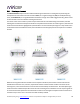
For example, if using the Chair listening environment, spread the microphone positions over a circle with a
diameter of a meter (three feet). Vary the height of the microphone up and down by 30 cm (one foot) from the
initial position. If using the Sofa or Auditorium listening environment, again spread the measurement locations
over the full listening area and vary microphone height by a significant amount.
A different set of locations other than those indicated by the visual guide and the above guidelines can be used
if necessary. The important thing is to ensure that the measurement locations are spread out over the whole
listening area and that the microphone is moved a sufficient distance vertically as well as horizontally.
In some cases, such as when the listening area is very close to the loudspeakers or the loudspeakers have a very
narrow dispersion pattern, the size and in particular the height of the measurement area can be reduced, to
avoid discrepancies caused by varying output response from the speakers themselves.
3.4.2 Executing measurements
With the microphone in place at the central location and pointed vertically (that is, towards the ceiling or floor),
click on the Start button. The DDRC-88A will generate a test signal, audible as a frequency sweep through the
left speaker, then the right, and so on through all channels. Finally, the frequency sweep plays through the left
speaker again.
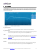
While the measurement proceeds, the time-domain response graph of the captured audio signal is displayed at
the bottom of the measurement tab. (This graph is related to the magnitude response but is not the same
display. Its purpose is to verify that the recorded signal level is in a suitable range.)
After completion of the measurement sweeps, the status bar will update with a progress indicator as the
program performs calculations on the measurement. If the measurement was successfully captured, the red
arrow marker will advance to the next location to be measured.
If the program indicates that the measurement was not successful, you will need to take corrective action. The
most common errors are related to signal level:
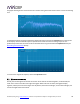
The measurement signal is too low to ensure a clean capture.
The measurement signal is too high and the audio signal has exceeded the maximum level (clipping). This is
shown in red on the signal graph.
In either of the above cases, go back to the Output & Levels tab and adjust Output volume, Input gain, or the
Channel volume slider for the channel that caused the problem. Then re-run the measurement. (You do not
need to redo the measurements you have already successfully completed.)