PRELIMINARY AND SUBJECT TO CHANGE DDRC-88A 8-CHANNEL AUDIO PROCESSOR WITH DIRAC LIVE® TECHNOLOGY User Manual PRELIMINARY AND SUBJECT TO CHANGE miniDSP Ltd, Hong Kong / www.minidsp.
PRELIMINARY AND SUBJECT TO CHANGE Revision history Revision 0.1 0.2 Description First draft Preliminary pre-release version Date 25 November 2014 5 December 2014 miniDSP Ltd, Hong Kong / www.minidsp.
PRELIMINARY AND SUBJECT TO CHANGE TABLE OF CONTENTS Important Information......................................................................................................................................... 5 System Requirements ...................................................................................................................................... 5 Disclaimer/Warning ..........................................................................................................................
PRELIMINARY AND SUBJECT TO CHANGE 4.2.3 Guidelines for target curve design .............................................................................................. 31 4.2.4 Saving and loading target curves ................................................................................................. 32 4.3 Generating correction filters............................................................................................................... 33 4.4 Downloading and managing filter sets ..........
PRELIMINARY AND SUBJECT TO CHANGE IMPORTANT INFORMATION Please read the following information before use. In case of any questions, please contact miniDSP via the support portal at minidsp.desk.com.
PRELIMINARY AND SUBJECT TO CHANGE Warning: This equipment has been tested and found to comply with the limits for a Class B digital device, pursuant to Part 15 of the FCC Rules. These limits are designed to provide reasonable protection. This equipment generates, uses and can radiate radio frequency energy and, if not installed and used in accordance with the instructions, may cause interference to radio communications.
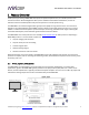
PRELIMINARY AND SUBJECT TO CHANGE 1 PRODUCT OVERVIEW Thank you for purchasing a DDRC-88A audio processor powered by Dirac Live®, the world’s premier room correction solution. We are delighted to offer you this software and hardware combination, the fruit of extensive research and development and years of experience in sound system tuning. The DDRC-88A is an 8-channel digital audio signal processor (DSP) running the Dirac Live® room correction algorithm.
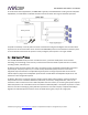
PRELIMINARY AND SUBJECT TO CHANGE In sound reinforcement applications, the DDRC-88A is typically connected between a mixing console and power amplification, as shown below. Individual channels can be set for either full-range or subwoofer operation. Computer connectivity is used to perform acoustic measurements and generate digital room correction filters. Up to four sets of correction filters can be stored on the DDRC-88A processor and recalled from the front panel or via an infrared remote.
PRELIMINARY AND SUBJECT TO CHANGE Illustration of Dirac Live® magnitude response correction Dirac Live® accomplishes this using mixed-phase filters – filters that match a desired magnitude response and generate a customized impulse response. This contrasts with the minimum-phase and linear-phase filters that are commonly used in audio applications.
PRELIMINARY AND SUBJECT TO CHANGE 1.3 DDRC-88A / DIRAC LIVE® CONFIGURATION STEPS The steps for configuring the DDRC-88A audio processor with Dirac Live® to optimize your home theater system is summarized as follows: 1. Connect the DDRC-88A audio processor into your system and install software. See Section 2, Installation and Setup. 2. Run a series of acoustic measurements using the Dirac Live Calibration Tool For miniDSP program, to capture the acoustic behavior of your speakers and room.
PRELIMINARY AND SUBJECT TO CHANGE 2 INSTALLATION AND SETUP 2.1 SOFTWARE INSTALLATION AND LICENSE ACTIVATION PRELIMINARY AND SUBJECT TO CHANGE 2.1.1 Framework installation Prior to installing the software, download and install the following frameworks. You will need to accept the license agreements in order to successfully complete the installation. If you haven’t updated these recently, check that you have the latest versions prior to running the miniDSP install programs. Microsoft .
PRELIMINARY AND SUBJECT TO CHANGE 2.1.3 License activation 1. Start the miniDSP DDRC-88A Utility program. It will appear as shown on the left below. 2. Connect your DDRC-88A processor to your computer via USB, then click on the Connect button. It will change to a green tick. 3. Click on Get Activation Serial Number. The program will get your unique serial number from the connected DDRC-88A and display it, as shown on the right below. 4.
PRELIMINARY AND SUBJECT TO CHANGE Notes: 1. The serial number that must be entered in the activation screen is not the serial number printed on the hardware unit. A unique serial number specific to Dirac Live is programmed into the firmware of each unit and can only be accessed with the DDRC-88A Utility program (step 3 above). 2. The email address and username used during license activation and validation are not related to your user account on miniDSP.com.
PRELIMINARY AND SUBJECT TO CHANGE 2.2 HARDWARE CONNECTIVITY All connections to the DDRC-88A are made on the rear panel. 2.2.1 Analog input and output Up to eight channels can be connected to the DDRC-88A. Single-ended connections are made directly to the RCA jacks. Balanced connections are made by connecting stripped wire ends directly to the Phoenix terminal blocks. miniDSP Ltd, Hong Kong / www.minidsp.
PRELIMINARY AND SUBJECT TO CHANGE Individual wires from the shielded pair cable are connected to each set of terminals as shown: Ensure that inputs and outputs are connected to the correct jack or set of terminals, or confusion will result when configuring the processor. This diagram shows the channel numbering on the rear panel. For information on input and output gain adjustments, see Optimizing gain structure. miniDSP Ltd, Hong Kong / www.minidsp.
PRELIMINARY AND SUBJECT TO CHANGE 2.2.2 DC Power Fit the supplied IEC cable to the 12 VDC power supply. Plug the DC connector into the +12VDC socket on the rear panel of the DDRC-88A, and then plug the AC mains plug into the power outlet. Apply power only after all analog input and output connections have been made. It is also strongly recommended that power amplification be powered on after all other equipment. 2.2.
PRELIMINARY AND SUBJECT TO CHANGE 3 ACOUSTIC MEASUREMENT The Dirac Live Calibration Tool For miniDSP uses a set of measurements made in your listening room to gather all the acoustical information about your room and speakers that it needs to calculate the correction filters. The measurements are made using the DDRC-88A processor and a miniDSP UMIK-1 measurement microphone (must be purchased separately). 3.
PRELIMINARY AND SUBJECT TO CHANGE 3.2 CONNECTIONS FOR ACOUSTIC MEASUREMENT The figure below shows a typical connection diagram for performing acoustic measurement. No changes to the audio connections are needed. Simply: 1. Connect the supplied USB (type A to type B) cable from the DDRC-88A to a USB port on the computer. 2. Connect a USB cable (type A to mini type B) from the UMIK-1 to a USB port on the computer.
PRELIMINARY AND SUBJECT TO CHANGE 3.3 CONFIGURING FOR MEASUREMENT Start Dirac Live Calibration Tool For miniDSP. Ensure that no other programs are running that may attempt to communicate with the DDRC-88A, such as the DDRC-88A Utility program, as this may result in communication conflicts and errors. Logo and status progress bar This area shows a progress bar with current status when the program is performing calculations. If the program seems unresponsive at any time, check the status here.
PRELIMINARY AND SUBJECT TO CHANGE 3.3.1 Sound System tab On the Sound System tab, set the following parameters. Choose system configuration Use the dropdown menu to select your system configuration. For multi-channel use, usually 5.1 or 7.1 will be selected. If you have a system configuration other than 5.1 or 7.1, use the Custom System option (see Custom System configuration below). Test signal playback device Preset to DDRC-88A (miniDSP Ltd).
PRELIMINARY AND SUBJECT TO CHANGE 3.3.2 Mic Config tab On the Mic Config tab, set the following parameters. Recording device Preset to the UMIK-1. If UMIK-1 is not showing, ensure that the UMIK-1 is connected securely to the computer via USB, and go back to the Sound System tab and click on Rescan. Then use the drop-down menu to select the “Microphone” item underneath “UMIK-1”.) Recording channel Select 1 from the drop-down menu.
PRELIMINARY AND SUBJECT TO CHANGE 3.3.3 Output & Levels tab On the Output & Levels tab, set Output volume quite low. If you have another volume control “down-stream” of the DDRC-88A, set it about halfway and increase it later if needed. Click on the Test button for the left channel and gradually increase the output volume until it is at a moderate level, such that your voice would have to be raised to converse with someone sitting next to you.
PRELIMINARY AND SUBJECT TO CHANGE 3.5 RUNNING THE MEASUREMENTS Measurements are performed on the Measurements tab. miniDSP Ltd, Hong Kong / www.minidsp.
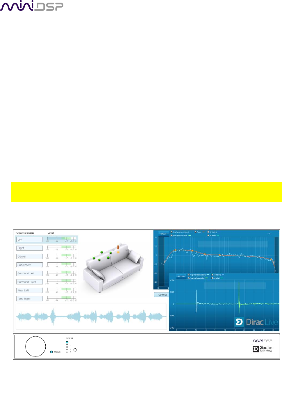
PRELIMINARY AND SUBJECT TO CHANGE 3.5.1 Listening environment The Measurements tab presents three different listening environments as a visual guide to positioning the microphone for each of the nine measurements: Chair, for a single listening seat; Sofa, for multiple listening seats; and Auditorium, for a large dedicated home theater or larger venue with staggered seating. Use the icons at the left of the screen to select the listening environment.
PRELIMINARY AND SUBJECT TO CHANGE While the locations indicated are recommended, you can use a different set of locations if necessary. The important thing is to ensure that the measurement locations are spread over the whole listening area and that the microphone is moved a sufficient distance vertically as well as horizontally.
PRELIMINARY AND SUBJECT TO CHANGE 3.5.3 Completing the measurements After each successful measurement, the location marker (red arrow) will advance to the next location. Move the microphone to that location, using the three views (top, front, oblique) as a guide to positioning it in the correct location. Then click on Start again. Repeat this process until all nine locations have been successfully measured.
PRELIMINARY AND SUBJECT TO CHANGE 4 FILTER DESIGN The Filter Design tab shows sets of graphs for the various 7.1 channels, selected using the tabs at the – click on these to display the response graphs for other channels (center, subwoofer, and surrounds). For each set of graphs, a number of variants can individually be turned on and off with the checkboxes above the graphs. Avg. spectrum (before) The average of the measured magnitude responses. These plots are shown in light blue. Avg.
PRELIMINARY AND SUBJECT TO CHANGE The graphs showing all nine measurements are useful for seeing how much variation there is across the listening area: To display the impulse response instead of the magnitude response, click on the Impulse button at the top left of the display. As with the magnitude response, the average measurement can be shown as well as all nine measurements.
PRELIMINARY AND SUBJECT TO CHANGE To unlink a channel, simply click on its chain icon. It will then be unlinked from the other channels. To link it to another channel or groups of channels, simply drag its tab on top of the channel or group of channels that you want it linked to. Initially, you may wish to link all speaker channels together, as shown at right in the diagram above, as this will make it easier to experiment with target curves.
PRELIMINARY AND SUBJECT TO CHANGE 4.2 DESIGNING YOUR TARGET CURVE The target curve is the desired in-room frequency response with the DDRC-88A processor performing digital room correction. 4.2.1 The Auto Target When first viewing the Filter Design tab, an estimated target curve suitable for your speakers is shown as the red curve. This calculated target curve can be restored at any time by clicking on the Auto Target button. Note: restoring the auto target will erase the current target curve.
PRELIMINARY AND SUBJECT TO CHANGE To alter the frequency region, drag the grey handles on either side of the graph. Note that you can’t drag these handles over an anchor point, so you may need to move or delete an anchor point that is “in the way.” If channels are linked, the same target curve is used for that group of linked channels. To create a separate target curve for a single channel, unlink it as described above in Working with graphs. 4.2.
PRELIMINARY AND SUBJECT TO CHANGE High-frequency “tilt” The target curve is the desired measured response of loudspeakers in a room, In contrast to measurements made of a loudspeaker during its design under anechoic (measured in free space) conditions.
PRELIMINARY AND SUBJECT TO CHANGE 4.3 GENERATING CORRECTION FILTERS Once you have a target curve set to your satisfaction, click on the Optimize button. The status bar will update as the algorithm progresses. The entire algorithm may take some time to complete, depending on the speed of your computer. When the algorithm completes, the predicted average magnitude response will be shown in green. (The predicted impulse response can be viewed by clicking on the Impulse button.
PRELIMINARY AND SUBJECT TO CHANGE 4.4 DOWNLOADING AND MANAGING FILTER SETS The Export tab initially shows four empty “slots” for filter sets (a filter set is one filter for every channel). Filter sets are managed with a “drag and drop” metaphor: To load the most recently generated filter set into the processor, drag the box at the top left (labeled “Auto target” in the example) and drop it onto an empty slot.
PRELIMINARY AND SUBJECT TO CHANGE 5 USING THE DDRC-88A AUDIO PROCESSOR Once the desired correction filters have been downloaded into the DDRC-88A audio processor, the computer is not required and can be disconnected. The front panel and/or an infrared remote can be used to control: Filter set selection Master volume Master mute (remote control only) Dirac Live® filtering bypass (remote control only) 5.
PRELIMINARY AND SUBJECT TO CHANGE 5.3 INFRARED REMOTE CONTROL Many standard and programmable remote control units can be used with the DDRC-88A processor. Instead of adding another remote to your collection, the processor can “learn” the control codes of your current infrared (IR) remote if it supports one of the following remote control codes: NEC Sony Philips RC6 Apple Remote Learning is done with the DDRC-88A Utility program. After starting the program, click on the Connect button.
PRELIMINARY AND SUBJECT TO CHANGE 6 OPTIMIZING GAIN STRUCTURE When deploying a DSP solution in your audio system, a topic that becomes more important than with analog equipment is gain structure. This means that the signal levels throughout the system should be set to an optimum – high enough to maximize digital resolution and minimize noise, but not so high as to result in clipping and distortion. 6.1 INPUT SENSITIVITY By default the input sensitivity of the DDRC-88A is 2 VRMS on the single-ended inputs.
PRELIMINARY AND SUBJECT TO CHANGE 6.2 OUTPUT GAIN By default, the maximum output signal level of the DDRC-88A is 2 VRMS on the RCA jacks, and 8 VRMS on the balanced connectors. These levels are compatible with the majority of consumer and pro-audio equipment respectively. If, however, a lower output level is required on any channel, the output gain can be reduced to 0.9 VRMS and 4 VRMS with the use of a DIP switch on the circuit board, as shown here: miniDSP Ltd, Hong Kong / www.minidsp.
PRELIMINARY AND SUBJECT TO CHANGE 7 ADDITIONAL INFORMATION 7.1 SPECIFICATIONS Computer connectivity Driverless USB 2.0 control interface for Windows and Mac OS X Analog inputs 8 x Balanced (Terminal Block) or 8 x Unbalanced (RCA) inputs Analog outputs Maximum balanced input voltage: 8 VRMS Maximum unbalanced input voltage: 2.0 or 0.9 VRMS (jumper selectable) 8 x Balanced (Terminal Block) and 8 Unbalanced (RCA) outputs Maximum balanced output voltage: 4.0 or 8.
PRELIMINARY AND SUBJECT TO CHANGE 3 The license validation screen doesn’t accept my username and password c. The “username” must be the email address that you used when activating your license on the Dirac Live activation screen. Check that you are using the same email address and password. 4 The DDRC-88A doesn’t appear in the Sound System tab d. Check that the USB cable to the DDRC-88A is firmly connected. e.
PRELIMINARY AND SUBJECT TO CHANGE 7.3 MCU FIRMWARE UPGRADE miniDSP may periodically provide an update to the DDRC-88A MCU firmware to enable new features. To update the MCU firmware, download the latest version of the DDRC-88A configuration plugin from the User Downloads section of the miniDSP.com website. Unzip the download and run the installer. Then follow the steps below. Note that the firmware upgrade tool is, as of publication of this User Manual, available on Windows only. 1. 2. 3. 4. 5.
PRELIMINARY AND SUBJECT TO CHANGE 7. Click on the Connect button. The status display should change to show that the program has connected: 8. Click the Load Hex File button. Browse to the firmware file located in the unzipped download and select it. The file will have name like DDRC_88A_v1_17_Released_13Nov2014.hex. The status will show that the hex file has loaded successfully: miniDSP Ltd, Hong Kong / www.minidsp.
PRELIMINARY AND SUBJECT TO CHANGE 9. Click the Erase-Program-Verify button. The progress bar will update. After some time, the status will update to show successful completion. DO NOT DISCONNECT THE USB CABLE OR POWER FROM THE DDRC-88A WHILE THIS IS IN PROGRESS. DOING SO MAY “BRICK” YOUR DDRC-88A. 10. Click the Run Application button to reboot the DDRC-88A. 11. Click the Disconnect button 12. Close the PIC32UBL application.