
User manual


Table Of Contents
- Important Information
- 1 Product Overview
- 2 Installation and Setup
- 3 Acoustic Measurement
- 4 Filter Design
- 5 Using the DDRC-88A audio processor
- 6 Optimizing gain structure
- 7 Additional Information
PRELIMINARY AND SUBJECT TO CHANGE
miniDSP Ltd, Hong Kong / www.minidsp.com / Features and specifications subject to change without prior notice 18
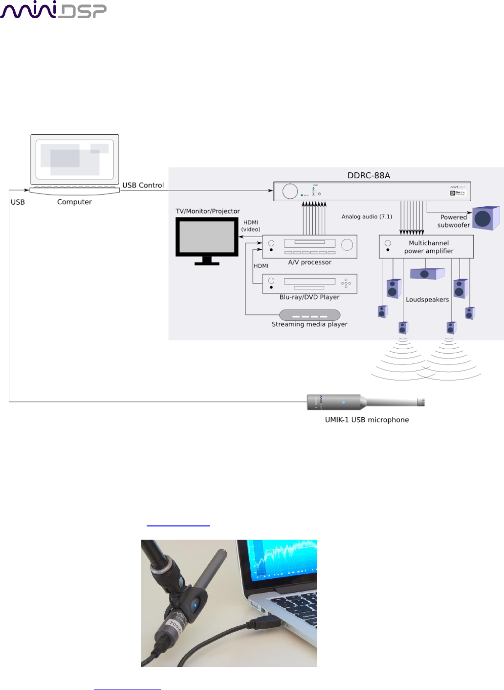
3.2 CONNECTIONS FOR ACOUSTIC MEASUREMENT
The figure below shows a typical connection diagram for performing acoustic measurement. No changes to the
audio connections are needed. Simply:
1. Connect the supplied USB (type A to type B) cable from the DDRC-88A to a USB port on the computer.
2. Connect a USB cable (type A to mini type B) from the UMIK-1 to a USB port on the computer.
Place the UMIK-1 microphone into a microphone stand and position the computer and cabling so that there is
enough freedom of movement to move the microphone into the needed locations. A small tripod stand is
supplied with the UMIK-1, but a larger stand with boom arm can be used if desired. If necessary a USB extension
(up to a total USB cable length of 5 meters) can be used. In larger spaces, an active USB repeater may be
needed. We recommend that the microphone be oriented vertically (pointed at the floor or ceiling) and the “90
degree” calibration file used (see Mic Config tab below).