
Instructions / Assembly

INSTALLATION INSTRUCTIONS FOR 1137-84
WARNING! SHUT POWER OFF AT FUSE OR CIRCUIT BREAKER .
AVERTISSEMENT! COUPER LE COURANT AU NIVEAU DES FUSIBLES OU DU DISJONCTEUR.
READ AND SAVE THESE INSTRUCTIONS
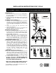
Fig.1
PREPATION (Fig. 1)
1. Shut off the power at the fuse box or circuit breaker
box. If necessary, remove the old fixture including the
mounting hardware.
2. Carefully remove the new fixture from the carton and
check that all parts are included as shown in the
illustration.
ASSEMBLING THE FIXTURE(Fig.1)
3. Determine the desired hanging height and thread
rods (G, H, I, J) onto the nipple (K). Carefully pass
the wires through each rod as you assemble. Please
remove the nipple if installing with one 6” or 12” rod
only.
4. Loosen the screws (D) (Size: #5-32*0.4”L), and
remove the canopy (C).
5. Slip the canopy (C) over the last rod installed, and
thread the nipple (F) onto the top of the rod.
MOUNTING THE FIXTURE (Fig.1)
6. Raise the mounting plate (A) to the junction box (not
provided), then secure with the junction box screws
(B) (Size: #8-32*0.6”L). The side of the mounting plate
marked “GND” must face out.
7. Install the fixture body into the mounting plate (A) by
tilting at a slight angle so that the hanger ball (E)
slips into the mounting plate (A) as shown. Align the
notch in the hanger ball (E) to the tab on the
mounting plate (A) to prevent the fixture from turning.
CONNECTING THE WIRES (Fig.2)
8. At this point, connect the electrical wires as shown in
figure 2, making sure that all wire connectors are
secured. If your outlet has a ground wire (green or
bare copper), connect the ground wires from the
hanger ball and mounting plate to it. Otherwise,
connect the ground wire from the hanger ball directly
to the mounting plate ground wire and secure with
the wire connectors provided. After wires are
connected, tuck them carefully into the ceiling
junction box.
COMPLETING THE INSTALLATION (Fig. 1)
9. Raise the canopy (C) to the mounting plate (A) and
align the mounting screws (D) to the slots (L). Then
turn canopy (C) clockwise until mounting screws (D)
are in the narrow part of slots (L). Tighten mounting
screws (D) with a screwdriver.
10. Install the light bulbs (included) in accordance with
the fixture’s specifications. (DO NOT EXCEED THE
MAXIMUM WATTAGE!) (NE PAS DEPASSER LA
PUISSANCE NOMINALE MAXIMALE!)
Note: Press spring coupling (M) by hand and
adjust to the desired length of steel wire (N).
Your installation is now complete. Return power to the
junction box and test the fixture.
Fig.2
W30-1-84
W30-H-84
Set# LTG BKT 10
- Mounting strap
- Ground screw
- Mounting screws*2
- Junction box screws*2