Model NO.
©2021 Minka Lighting Inc. Manual design and all elements of manual design are protected by United States Federal and/or State Law including Patents, Trademark, and/or Copyright Laws.
The Minka-Aire® warranty is for one (1) year from the date of purchase from an authorized Minka-Aire® dealer. This warranty is only valid to the original purchaser or user against all defects in material and workmanship (light bulbs excluded) for one (1) full year. Additionally, Minka-Aire® warrants the motor only for the lifetime of the Minka Aire ceiling fan (excluding wall controls and electrical components), to the original purchaser or user.
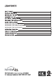
6 INSTALLING THE LIGHT KIT PLATE INSTALLING THE 16W LED ASSEMBLY INSTALLING THE GLASS SHADE 8 9 10 14
READ AND SAVE THESE INSTRUCTIONS. 1. To reduce the risk of electric shock, ensure electricity has been turned off at the circuit breaker or fuse box before beginning. 2. All wiring must be in accordance with the National Electrical Code “ANSI/NFPA 701999” and local electrical codes. Electrical installation should be performed by a qualified licensed electrician. 3. The outlet box and support structure must be securely mounted and capable of reliably supporting a minimum of 35 Ibs.
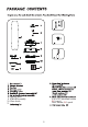
3 8. Light kit plate 9. 16W LED assembly 10. Glass shade 11. 3/16”x12.
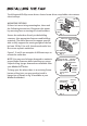
Tools Required: Phillips screw driver; slotted screw driver; step-ladder; wire cutters; electrical tape. MOUNTING OPTIONS If there isn't an existing mounting box, then read the following instructions. Disconnect the power by removing fuses or turning off circuit breakers. Secure the outlet box directly to the building structure. Use appropriate fasteners and building materials. The outlet box and its support must be able to fully support the moving weight of the fan (at least 50 lbs.).
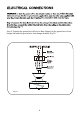
WARNING: All of the parts, hardware and components such as the hanger bracket and hanger ball have been provided for your safety and the proper installation of your new ceiling fan. The use of other parts, hardware or components not supplied by Minka Aire®with the fan will void the Minka Aire® Warranty. REMEMBER to turn off the power. Follow the steps below to hang your fan properly: OUTLET BOX Step 1.
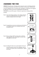
Step 5. Slip coupling cover, canopy cover and canopy onto downrod. (Fig. 9) Carefully reinstall hanger ball onto rod being sure that cross pin is in the correct position, set screws are tighten and wires are not twisted. DOWNROD CANOPY COUPLING COVER CANOPY COVER SET SCREWS LOCK PIN Fig. 9 Step 6. Now lift motor assembly into position and place hanger ball into hanger bracket. Rotate until the check groove has dropped into the registration slot and seats firmly. (Fig.
.11 Step 2. Connect the ground wire (Green or Bare Copper) to the ground wire from hanger ball and the ground wire from hanger bracket. (Fig.11) Fig.
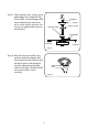
12 12 OUTLET BOX HANGER BRACKET HANGER BALL CANOPY CANOPY COVER Fig. 12 Step 1. Insert the blade through the slot on the fan motor assembly. (Fig.13) Step 2. Attach the fan blade to the fan motor assembly using the three blade screws and three fiber washers securely. (Fig.13) Step 3. Repeat this step with the other two blades. (Figure 13) FIBER WASHER FAN MOTOR ASSEMBLY BLADE SCREW BLADE Fig.
INSTALLING THE LIGHT KIT PLATE CAUTION: To Reduce The Risk Of Electric Shock, Disconnect The Electrical Supply Circuit To The Fan Before Installing Light Kit. 1 14 Step 2. While holding the light kit plate under your fan, firmly snap the wire connection plugs together. (Fig.14) 3 14 MOUNTING RING CONNECTION PLUG CONNECTION PLUG LIGHT KIT PLATE SCREW Fig.
INSTALLING THE 16W LED ASSEMBLY CAUTION: To Reduce The Risk Of Electric Shock, Disconnect The Electrical Supply Circuit To The Fan Before Installing Light Kit. Step 1. Remove 1 of 3 screw from the pillar of light kit plate and loosen the other 2 screws. (Do not remove) (Fig.15) 2 16W LED assembly 15 Step 3.
INSTALLING THE GLASS SHADE Attach the glass shade to the light kit plate by twisting tightly. (Fig.16) (Fig.
The Reverse switch is located on light kit assembly (Fig.18). Slide the switch to the Left for warm weather operation. Slide the switch to the Right for cool weather operation.
WARNING! MAKE SURE THE POWER IS OFF AT THE ELECTRICAL PANEL BOX BEFORE YOU ATTEMPT ANY REPAIRS. REFER TO THE SECTION, “ELECTRICAL CONNECTIONS”.
13
120 0.26 14.36 81 6.68 9.28 54 120 0.53 63.67 178 3,320 11 82 41 1,988 14.36 138 4,495 63.67 70 14 1.