©2020 Minks Lighting Inc. Manual design and all elements of manual design are protected by United States Federal and/or State Law including Patents, Trademark. and/or Copyright Laws.
. The Minka-Aire® warranty is for one (1) year from the pilfer me > date of purchase from an authorized Minka-Aire® dealer. This warranty is only valid to the original purchaser or user against all defects in material and workmanship {light bulbs excluded) for one (1) full year. Additionally, Minka-Aire® warrants the motor only for the lifetime of the Minks Ire ceiling fan (excluding wall controls and electrical components), to the original purchaser or user.
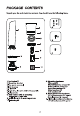
CONTENTS SAFETY RULES __ PACKAGE CONTENTS INSTALLING THE MOUNTING BRACKET ELECTRICAL CONNECTIONS .. INSTALLING THE WALL CONTROL FINISHING THE INSTALLATION ATTACHING THE FLYWHEEL AND FAN BLADES REMOVING THE 16W I.ED ASSEMBLY FROM LIGHT KIT PLATE. INSTALLING THE LIGHT KIT PLATE .. INSTALLING THE 16W LED ASSEMBLY. . INSTALLING THE GLASS SHADE OPERATING YOUR FAN. CARE OF YOUR FAN .. TROUBLESHOOTING . SPECIFICATIONS miniature, 1151 W.
SAFE TY RULES Before you begin installing the fan, shut power off at the circuit breaker of the fuse box. 2. Be cautious! Read all instructions and safety information before installing your new fan. Review accompanying assembly diagrams. 3. Make sure that all electrical connections comply with local codes, ordinances, or National Electrical Codes. Hire a qualified electrician or consult a do-it-yourself wiring handbook if you are unfamiliar with installing electrical wiring. 4.
PACKAGE CONTENTS Unpack your fan and check the contents. You should have the following items: :J——Lu Fan blades{3) A. Mounting hardware: 2 Mounting bracket Wire nuts(3) 3. Fan motor assembly screws (2) 4. Fan housing #10x1.5Waod screws (2) 5. Flywheel :flmhr;nlsur @2 6. Light kit plate with 16W LED assembly 7 Glass shade . B. Blade attachment hardware: 8. Wall control \mt 2 mounting screws (9+1 spare) screws and 5 wire nuts Metal washers {9+1 spare) 9. Wall plate with 2 mounting screws €.
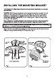
INSTALLING THE MOUNTING BRACKET Tools Required: Phillips screw driver: slotted screw driver; step-ladder; wire cutters; electrical tape. WARNING: All of the parts, hardware and components have been provided for your safety and the proper installation of your new ceiling fan. The use of other parts, hardware or components not supplied by Minks Aire® with the fan will void the Minks Aire® Warranty. REMEMBER To tum off the power. Follow the steps below to hang your fan properly. Step 1.
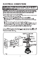
ELECTRICAL CONNECTIONS WARNING: HOOK UP IN "SERIES ONLY" DO NOT CONNECT THE HOT AND NEUTRAL WIRES OF ELECTRIC CIRCUIT TO THE WALL CONTROL DAMAGE TO THE SWITCH AND POSSIBLE FIRE COULD OCCUR. REMEMBER to shut the power off at the circuit breaker or fuse box. Follow the steps below to connect the fan to your house supply wires. Use the wire nuts supplied with your fan. Secure the wire nuts by wrapping the connection with electrical tape. Proceed to make the wire conventions as follows: a.
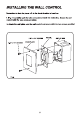
INSTALLING THE WALL CONTROL Remember to shut the power off at the circuit breaker or fuse box. 4 ) Carefully tuck the wire connections inside the outlet box. Secure the wall control with the two screws provided. 2. Attach the wall plate over the wall control and secure with the two screws provided.
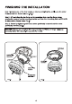
FINISHING THE INSTALLATION Step 1. Remove one of the four screws on the mounting bracket and loosen the other three screws, but do not remove. (Fig.5) Step. Lift and place the key holes on the mounting plate over the three screws previously loosened on the mounting bracket and turn the mounting plate until it locks in place and no longer tums. (Fig.5) Step 3. Secure by tightening the three screws previously loosened and the screw previously removed. (Fig.
Step 4. Pay attention to the four large screw heads Pr-locked on the fan housing and the four key holes on the mounting bracket. they will be needed to be locked together after finished the wire connection in step 7 Step 5. Firmly snap the wire connection plug from fan motor assembly to the wire connection plug from fan housing. {Fig.8) Make Sure the wire connections are not in the way of the housing as you lift the housing and proceed to Step 8. Step 6.
ATTACHING THE FLYWHEEL AND FAN BLADES Step 1. Pay attention to the labels named 'flywheel screw’ on the motor and the flywheel. Start from this label and align the three holes on the motor to the three holes on the flywheel. Tighten them using with three flywheel screws (174"x6mm) securely. (Fig.10) Important: do not use wrong screw in this step. If using blade screws which is longer than flywheel screw ta install the flywheel by mistake, it will damage the copper wire inside the motor.
REMOVING THE 16W LED ASSEMBLY FROM LIGHT KIT PLATE Step 1. Remove the screw from circular hole of light kit plate and loosen the other two screws from key holes approximately 174 tum. Keep the screw that removed aside for use later. Step 2. Tum the key holes of 16W LED assembly from the two screws loosened previously and remove the 16W LED assembly from the light kit plate. {Fig.12) LIGHT KIT PLATE Flg.12 CIRCULAR HOLE 8 SCREW INSTALLING THE LIGHT KIT PLATE Step 1.
INSTALLING THE 16W LED ASSEMBLY Step 1. While holding the 16W LED assembly under your fan firmly snap the wire connection plugs together. Step 2. Place the key holes from 16W LED assembly over the two screws previously loosened from the light kit plate Tum the 16W LED assembly until it locks at the narrow section of the key holes. Secure by tightening the two screws previously loosened and the one screw previously removed. (Fig.
INSTALLING THE GLASS SHADE Attach the glass shade to the light kit plate by twisting tightly.
OPERATING YOUR FAN Restore power to ceiling fan and test for proper operation. Speed settings for warm or cool weather depend on factors such as the room size. Ceiling height. number of fans, etc. Tum on the power and check the operation of your fan. The fan 4-speed control is used to set the fan speed as follows {Fig.16): -~ =Turns the fan off 1= High Speed 2= Medium High Speed tedium Speed 4= Low Speed will control the lights, brightness dimmer and off.
CARE OF YOUR FAN Here are some suggestions to help maintain your fan, 1.Because of the fan's natural movement some connections may become loose. Check the support connections, brackets and blade attachment twice a year. Make sure they are is not necessary to remove fan from the ceiling}. 2.Clean your fan periodically to help maintain its new appearance over the years. Use only a soft brush or lint free cloth to avoid scratching the finish.
TROUBLESHOOTING SYMPTOM Fan will not start SOLUTION ® Check to make sure the wall switch is muted on. ® Check circuit fuses or breakers. * Caution Make sure the power is muted off before performing the following steps. SYMPTOM Fan Sounds Noisy SOLUTION » Allow a 24 hour " break in” period. Most noises associated with a new fan will go away during this time. * Make sure the screws that attach the fan blade holder to the motor hub is tight.
SPECIFICATIONS These are typical readings. Your actual fan may vary. They do not include am and wattage used by the light {s). Y P Fan Size Speed Volts Amps Watts RPM NW. GW. CF Low 120 019 M46 83 658 902 48" kgs kgs 206’ High 120 035 4244 189 PERFORMANCE AND ENERGY INFORMATION Estimated Airflow Yearly Energy Cost 2,307 $8 carmine Y T far o anon, e ) Cont Range o Liker e (11" —84% Ford P e Poc FAN SPEED AIRFLOW POWER USE AIRFLOW EFFICIENCY {CF* (watts) {(CFMiwat1) Low 1577 146 137 High 3.