Model NO.
This product is protected by United States Federal and/or State Law including Patents, Trademark, and/or Copyright Laws. ©2020 Minka Lighting Inc. Manual design and all elements of manual design are protected by United States Federal and/or State Law including Patents, Trademark, and/or Copyright Laws.
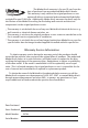
The Minka-Aire® warranty is for one (1) year from the date of purchase from an authorized Minka-Aire® dealer. This warranty is only valid to the original purchaser or user against all defects in material and workmanship (light bulbs excluded) for one (1) full year. Additionally, Minka-Aire® warrants the motor only for the lifetime of the Minka Aire ceiling fan (excluding wall controls and electrical components), to the original purchaser or user.
INSTALLING THE PC LAMP SHADE 14
1. Before you begin installing the fan, shut power off at the circuit breaker of the fuse box. 2. Be cautious! Read all instructions and safety information before installing your new fan. Review accompanying assembly diagrams. 3. Make sure that all electrical connections comply with local codes, ordinances, or National Electrical Codes. Hire a qualified electrician or consult a do-it-yourself wiring handbook if you are unfamiliar with installing electrical wiring. 4.
3 18 mm blade screws 6+1 spare Metal washer (6+1 spare) 9. PC lamp shade 10.
Tools Required: Phillips screw driver; slotted screw driver; step-ladder; wire cutters; electrical tape. MOUNTING OPTIONS If there isn't an existing mounting box, then read the following instructions. Disconnect the power by removing fuses or turning off circuit breakers. Secure the outlet box directly to the building structure. Use appropriate fasteners and building materials. The outlet box and its support must be able to fully support the moving weight of the fan (at least 50 lbs.).
Step 1. Attach the fan blade to the fan motor assembly by using two blade screws and metal washers. Tighten all screws and washers securely. Note: When installing the blades, ensure the sides with “THIS SIDE UP” face the ceiling. BLADE SCREW METAL WASHERS ESTA GETTE THLS SIDE UP LADO HACIA ARRIBA EACE VERS EN HAUT BLADE FAN MOTOR ASSEMBLY Fig.
WARNING: All of the parts, hardware and components such as the hanger bracket and hanger ball have been provided for your safety and the proper installation of your new ceiling fan. The use of other parts, hardware or components not supplied by Minka Aire®with the fan will void the Minka Aire® Warranty. REMEMBER to turn off the power. Follow the steps below to hang your fan properly: OUTLET BOX Step 1.
Step 5. Slip coupling cover, canopy cover and canopy onto downrod. (Fig. 10) Carefully reinstall hanger ball onto rod being sure that cross pin is in the correct position, set screws are tighten and wires are not twisted. DOWNROD CANOPY COUPLING COVER CANOPY COVER SET SCREWS LOCK PIN Fig. 10 Step 6. Now lift motor assembly into position and place hanger ball into hanger bracket. Rotate until the check groove has dropped into the registration slot and seats firmly. (Fig.
.12 Step 2. Connect the ground wire (Green or Bare Copper) to the ground wire from hanger ball and the ground wire from hanger bracket. (Fig.12) Fig.
13 13 OUTLET BOX HANGER BRACKET HANGER BALL CANOPY CANOPY COVER Fig.
CAUTION: To Reduce The Risk Of Electric Shock, Disconnect The Electrical Supply Circuit To The Fan Before Installing Light Kit. Step1. Remove the screw from circular hole and loosen the other two screws from key holes approximately 1/4 turn. Keep the screw that removed aside for use later. Step2. Turn the key holes of the light kit assembly from the two screws loosened previously and remove the light kit plate from light kit assembly. (Fig.
INSTALLING THE PC LAMP SHADE Pay attention to the slot on the light kit plate with the black dot label . Rotate the PC lamp shape until its groove lock into the slot and seats firmly. (Fig.
The Reverse switch is located on light kit assembly (Fig.18). Slide the switch to the Left for warm weather operation. Slide the switch to the Right for cool weather operation.
WARNING! MAKE SURE THE POWER IS OFF AT THE ELECTRICAL PANEL BOX BEFORE YOU ATTEMPT ANY REPAIRS. REFER TO THE SECTION, “ELECTRICAL CONNECTIONS”.
13
120 0.22 13.35 84 5.22 44 120 0.44 52.91 171 2,386 10 69 34 1354 13.35 101 3278 52.91 61 14 6.63 1.