RIPTIDE ULTERRA ® WITH i-PILOT ® BOW-MOUNT TROLLING MOTOR OWNER'S MANUAL ™
CE MASTER USER MANUAL (FOR CE/C-TICK CERTIFIED MODELS) CE MASTER USER MANUAL CERTIFIED MODELS) Conforms to 89/336/EEC (EMC)(FOR under CE/C-TICK standards EN 55022A, EN 50082-2 since 1996 LN V9677264 Conforms to 89/336/EEC (EMC) under standards EN 55022A, EN 50082-2 since 1996 LN V9677264 CE MASTER USER MANUAL (FOR CE/C-TICK CERTIFIED MODELS) THAnK YOU Conforms 89/336/EEC (EMC) under standards EN 55022A, EN 50082-2 since 1996 LN V9677264 THAnKto YOU Thank the Minn electric steer trolling motor.
Table of Contents Introduction Two-Year Limited Warranty 2 4-5 Warranty on Minn Kota i-Pilot® Wireless GPS Trolling System 4 Warranty on Minn Kota Saltwater Trolling Motors 5 Features 6 Installation 7-10 Battery & Wiring Installation 11-12 Boat Rigging & Product Installation 11 Conductor Gauge and Circuit Breaker Sizing Table 11 Selecting the Correct Batteries 12 How to Connect Batteries 12 Motor Wiring Diagram Getting Started 13 14-19 Getting Star
Two-Year Limited Warranty WARRAnTY On mInn KOTA i-PILOT® AnD i-PILOT® LInK™ WIRELEss gPs TROLLIng sYsTEm ACCEssORY Johnson Outdoors Marine Electronics, Inc. (“JOME”) extends the following limited warranty to the original retail purchaser only. Warranty coverage is not transferable.
Two-Year Limited Warranty WARRAnTY On mInn KOTA sALTWATER TROLLIng mOTORs Johnson Outdoors Marine Electronics, Inc. (“JOME”) extends the following limited warranty to the original retail purchaser only. Warranty coverage is not transferable.
FEATURES MOTOR FEATURES Integrated i-Pilot Control Head Power Trim i-PILOT ULTERRA REMOTE Auto Stow/Deploy For complete details on this remote, see page 16 of this manual. Lifetime Warranty Flexible Composite Shaft Trim Up Trim Down Stow/Deploy Weedless Wedge 2 Propeller Cool Quiet Power Motor Specifications subject to change without notice. *This diagram is for reference only and may differ from your actual motor. 6 | minnkotamotors.com ©2015 Johnson Outdoors Marine Electronics, Inc.
Installation PARTs InCLUDED Your new Riptide Ulterra comes out of the box with everything you’ll need for direct to boat mounting. This motor can be direct mounted to the boat or coupled with a Minn Kota quick release bracket for ease of mounting and removal. For compatible quick release mounting brackets and to locate your nearest dealer, visit minnkotamotors.com. Please review the parts list and tools needed for installation prior to getting started. PARTs LIsT A. (1) Riptide Ulterra Trolling Motor B.
Installation Ulterra Installation Guide Parts Included: Description Qty. Screw, 1/4-20 x 2” HHCS SS 6 Screw, 1/4-20 x 0.5 HHCS SS 6 Washer-Clipped, 1/4”, 1” OD 6 Nut, 1/4-20 Nylock SS 6 Washer, 1/4” Flat 18-8 SS 6 Washer-Mounting, Rubber 6 Tools and Resources Required: • • • • • • • Drill 5/16” Drill Bit 7/16” Wrench 9/16” Wrench (for prop) Wire Ties (for cable routing) Phillips Screwdriver Flat Blade Screwdriver Installation Instructions: 1. Remove the four sideplate screws.
Installation 4. Once the motor is positioned, mark at minimum, four of the six holes that are located farthest apart (at least two on each side). Make sure the area under the mounting location is clear to drill holes and install nuts and washers. Drill through the marked holes using a 5/16” drill bit. 5. Mount the motor to the boat using the provided hardware. Install the hex head bolts and clipped washers on the right side of the motor as viewed from the boat interior.
Installation mOUnTIng OPTIOns The user has the option of stowing with the prop oriented in or out to accommodate different boat cover configurations. Follow the procedure below to change prop orientation. 1. Turn power on and deploy motor using the stow/deploy button on the remote (see the Manual Control section or Ulterra Functions for deploying instructions). CAUTION: When deploying, ensure the motor doesn’t contact boat or trailer. 2. Turn the motor off. 3.
Battery Wiring & Installation bOAT RIggIng & PRODUCT InsTALLATIOn For safety and compliance reasons, we recommend that you follow American Boat and Yacht Council (ABYC) standards when rigging your boat. Altering boat wiring should be completed by a qualified marine technician. The following specifications are for general guidelines only: CAUTION: These guidelines apply to general rigging to support your Minn Kota motor.
Battery Wiring & Installation sELECTIng THE CORRECT bATTERIEs The motor will operate with any lead acid, deep cycle marine 12 volt battery/batteries. For best results, use a deep cycle, marine battery with at least a 105 ampere hour rating. Maintain battery at full charge. Proper care will ensure having battery power when you need it, and will significantly improve the battery life. Failure to recharge lead-acid batteries (within 12-24 hours) is the leading cause of premature battery failure.
Motor Wiring Diagram NOTE: This is a universal, multi-voltage diagram. Double-check your motor's voltage for proper connections. Over-Current Protection Devices not shown in this illustration.
GETTING STARTED GETTING STARTED WITH THE ULTERRA MOTOR MOTOR CONTROL PANEL POWER ON The Ulterra Trolling Motor must be powered “on” manually. The remote will not turn the motor on. The power button is located on the base of the motor. Pressing the power button will turn on Ulterra. The red STATUS light and the green SYSTEM READY light will both be illuminated when powered on. POWER OFF To power off Ulterra, press and hold the POWER button approximately three seconds, until the green light turns off.
gETTIng sECTIOnsTARTED TITLE Getting Started GETTING WITH THE i-PILOT REMOTE KnOWIngSTARTED YOUR REmOTE LAYOUT The i-Pilot remote is divided into four sections: Manual Control, Tracks, Spot-Lock, and Cruise Control/AutoPilot. Buttons in the Manual Control section of the remote do not require a GPS signal to operate and give you full, immediate control over steering, speed and prop functions similar to a CoPilot. All other buttons require a minimum GPS signal strength of one bar in order to operate.
Getting Started REmOTE COnTROL QUICK REfEREnCE gUIDE TRACKs mAnUAL COnTROL Track to End Navigates to the nearest location on a previously recorded track and follows it to its end. Steer Left Track to Start Navigates to the nearest location on a previously recorded track and follows it to its start. Steer Right Track Record Starts and ends the recording of a track to a selected memory location.
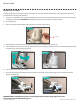
gETTIng Getting sTARTED Started REmOTE bATTERY REPLACEmEnT 1. Make sure hands are clean, dry and static free. Discharge any static electricity by touching a metal object that is grounded. NOTE: Static electricity can damage the circuit board. 2. With the remote upside down, use a large coin to rotate the battery door counterclockwise until either of the Unlock icons align with the arrow (see Figure B). FIGURE A 3. Remove battery cover and old battery and replace with new CR2450 coin cell battery.
Getting sTARTED gETTIng Started AUDIO mODEs The i-Pilot Controller also contains an internal speaker which can be programmed to work in two different audio modes. The speaker is and down at the same programmed to operate in audio mode one from the factory. To enable different audio modes hold time for three seconds. For an explanation of each audio mode and their sounds see the table below. 18 20 | minnkotamotors.com | minnkotamotors.
gETTIng sTARTED GETTING STARTED POWER The i-Pilot controller will turn on whenever the trolling motor has power. For Terrova and Riptide ST motors this is when the green system POWER ready light is on. For PowerDrive V2 and Riptide SP motors this is whenever the motor is connected to power.
MANUAL CONTROL MANUAL CONTROL FUNCTIONALITY This section describes all Manual Control functions of i-Pilot. A manual function is one in which the operator takes full control of the function such as manually steering the motor in a desired direction or manually adjusting the prop speed to the desired setting, trimming, stowing and deploying, or manually adjusting the prop speed. Any of these functions do not require a GPS signal. PROP ON/OFF To turn the prop on or off press .
MANUAL CONTROL TRIMMING UP AND DOWN There will be times when you will need to move your motor up or down depending on how your boat is responding. You can trim up to avoid hitting underwater objects and you can trim down if your prop is coming out of the water. Trim the motor up or down with the i-Pilot remote by pressing or . NOTE: The prop will temporarily stop while trimming the motor and resume once trimming is stopped. NOTE: Trim limits are in place to avoid damage to the unit.
gPssECTIOn mOTOR COnTROL TITLE UnDERsTAnDIng HOW THE i-PILOT sYsTEm WORKs nAVIgATIOn i-Pilot uses GPS satellite signals as well as digital compass data to know where it is, where it is heading and the direction the motor is pointing. Since i-Pilot depends on GPS satellite signals for navigation, a minimum GPS signal level of one bar is required in order for GPS navigation controls to be enabled. Best results are achieved when a GPS signal level of four bars can be obtained.
sECTIOn sPOT-LOCK TITLE HOW sPOT-LOCK WORKs sPOT-LOCK Spot-Lock uses a single point as a reference for the spot you want to stay on. This point is recorded and stored into one of the six memory locations when the Spot-Lock button is pushed. Around the Spot-Lock location i-Pilot uses an arrival circle to determine prop speed and direction. If i-Pilot sees it is within the circle, it will adjust the motor speed to zero.
SPOT-LOCK sPOT-LOCK sPOT-LOCK EngAgIng sPOT-LOCK EngAgIng on the remote. 1. Press sPOT-LOCK the remote. 1. 2. Press The Memoryon Location icon will flash on the remote LCD for three seconds, allowing you to choose a . Pressing again or waiting for three accepts the location by pressing 2. memory The Memory Location icon will flashoron the remote LCD for three seconds, allowing youseconds to choose a memory location. or .
CRUIsE sECTIOn COnTROL TITLE HOW CRUIsE COnTROL WORKs CRUIsE COnTROL i-Pilot automatically controls the motor speed to maintain a constant GPS speed. EngAgIng CRUIsE COnTROL 1. Press on the remote. 2. The current GPS speed will flash, displaying your current speed as the target GPS speed on the remote LCD for three seconds. or to increase or decrease the target speed or press 3. Press Cruise Control immediately. again to engage DIsEngAgE CRUIsE COnTROL 1. Pressing will disengage Cruise Control. 2.
sECTIOn AUTOPILOT TITLE HOW AUTOPILOT WORKs Two different versions of AutoPilot are available: AutoPilot and Advanced AutoPilot. There are distinct differences between the two AutoPilots and how they control your boat. AUTOPILOT AutoPilot uses an internal compass to provide heading lock. When AutoPilot is on, it keeps the motor pointed in the same compass direction. If a manual steering correction is made, AutoPilot locks onto the new compass heading to which the boat was steered.
AUTOPILOT EngAgIng ADVAnCED AUTOPILOT AnD AUTOPILOT 1. To engage Advanced AutoPilot, press for two seconds. once. To engage AutoPilot, press and hold 2. The Advanced AutoPilot or AutoPilot icon will be displayed on the remote LCD. 3. To adjust desired heading, manually steer motor to new heading. i-Pilot will lock onto new heading. Advanced AutoPilot DISENGAGING ADVANCED AUTOPILOT AND AUTOPILOT 1. Pressing will disengage AutoPilot. 2. Pressing will also disengage AutoPilot and stow the motor.
TRACK RECORDIng sECTIOn TITLE / PLAYbACK HOW TRACK RECORDIng AnD PLAYbACK WORK TRACK RECORDIng AnD PLAYbACK When the Track Record button is pressed, i-Pilot starts to record GPS position data in the form of track points. The distance between these points varies based on the speed of the boat and the GPS signal strength. The very first track point recorded is called the start. The last point recorded is called the end. i-Pilot sees a recorded track as a series of these track points.
TRACK RECORDIng / PLAYbACK RECORDIng A TRACK 1. Press TRACK RECORDIng / PLAYbACK on the remote. 2. The Memory Location icon will flash on the remote LCD for three seconds, allowing you to choose a RECORDIng A TRACK or . Pressing again or waiting for three seconds accepts memory location by pressing the remote. 1. the Press memory on location. 2. The The REC Memory icon will on flash the remote LCD for three allowing you to a 3. iconLocation will be displayed theonremote LCD.
TRACK RECORDIng / PLAYbACK REPLAYIng A TRACK (TRACK TO sTART / TRACK TO EnD) 1. Manually navigate the boat to within a quarter mile of the saved track. Due to safety reasons, i-Pilot will not re-engage a saved track greater than a quarter mile away. 2. Press or on the remote. 3. The Memory Location icon will flash on the remote LCD for three seconds, allowing you to choose a or .
Alternative Stowing Procedures STOWING FROM THE ULTERRA MOTOR In the unlikely event your remote becomes non-functioning, you can stow the Ulterra from the base of the motor by completing the following sequence: 1. Ensure that the motor is on. 2. Press and hold the POWER button located at the mounting base for 10 seconds. 3. The red and green LEDs will flash alternately, and motor will begin stow process.
Manual Stow Procedure In the unlikely event that the motor will not stow from either the remote or foot pedal command, the following alternative stow methods should solve the issue: 1. Trim/Stow Reset Procedure (see “Alternate Stowing Methods” section) 2. Stowing from the Motor (see “Alternate Stowing Methods” section) 3. If your batteries lose power to the level that the motor will not stow, the motor will most likely stall at a 45 degree angle.
Manual Stow Procedure 3. Pull manual trim handle out while lifting up on the trim housing until shaft and trim module can be pulled up by hand. (Figure 17) Figure 1717 Figure TrimTrim Housing Housing TrimTrim Handle Handle 4. While pulling up on the bracket to release the latch pin, rotate (Figure 18) and pull the lower unit onto the ramps. (Figures 19 & 20) Figure Figure18 18 Figure 19 19 Figure 5. Figure 2020 Figure Secure lower unit onto the ramps using the provided emergency strap.
Adjustments ADjUsTIng THE LIfT bELT Periodically slack may appear in the main lift belt, and it may occasionally require small adjustments to maintain belt tension. Using a 5/32” allen wrench turn the socket head cap screw, located on the bottom of the control head, clockwise (see Figure 23) until belt is finger tight and you can force finger under belt.
Service & Maintenance PROPELLER REPLACEmEnT Propeller TOOLS AND RESOURCES REQUIRED: • Box End Wrench - 1/2” for motors with 70 lbs thrust or lower. - 9/16” for motors with 80 lbs thrust or higher. • Screwdriver (optional) Anode/Nut Washer CAUTION: Disconnect the motor from the battery before beginning any prop work or maintenance. NOTE: The propeller on your motor may differ from the one pictured. Drive Pin 1. Disconnect motor from battery prior to changing the propeller. 2.
TROUBLESHOOTING ULTERRA 1. Motor fails to run or lacks power: • Check battery connections for proper polarity. • Are batteries charged? • Make sure terminals and wires are clean and corrosion free. Use fine sandpaper or emery cloth to clean terminals. • Check circuit protection devices. • Check battery water level. Add water if needed. 2. Motor loses power after a short running time: • Check battery charge. If low, restore to full charge, or replace. 3.
Troubleshooting i-PILOT gEnERAL TROUbLEsHOOTIng Problem: Solution: The motor is making erratic steering corrections while in AutoPilot, Spot-Lock or Track to Start/End. Be sure to keep all ferrous metallic objects away from the i-Pilot controller as they will have an impact on the built-in compass. Such objects include: anchors, metal framework, etc. Problem: Solutions: When a button on the remote is pressed the motor doesn’t always respond. Check if the low battery indicator is on.
Troubleshooting AUTOPILOT Problem: Solution: Problem: Solution: When in Advanced AutoPilot in strong winds, there is quite a bit of back and forth movement in the boat. While Advanced AutoPilot will keep your boat on a true heading, it may be at the expense of the boat having to continuously move to get back on the correct course. In these extreme conditions you may be better off using AutoPilot and correcting for the wind manually.
prop is off. Q: Which quick release brackets are compatible with Ulterra A: The following quick release brackets can be used with UIterra: MKA-32, MKA-16-02, RTA 17 and RTA 21. FAQ Q: Is there a manual Stow and Deploy procedure? A: Yes. There is a manual method for stowing Ulterra. See the Emergency Stow Procedure section for instructions. Q: When Ulterra is deployed, at what depth does the deploy stop? A: Ulterra will always deploy to the most recent depth that was used.
i-PILOT Q: Does i-Pilot record the speed I am traveling when recording a track? A: No. i-Pilot only records its location during track record. It is up to the user to set the desired speed manually or with Cruise Control. Q: Why doesn’t my GPS Signal Strength icon always show all four bars? A: GPS signal strength is impacted by many influences including: • i-Pilot controller having a clear view of the sky (especially to the southern sky), • Boat being located alongside a high bank • Your geographic location.
Parts Diagram RIPTIDE ULTERRA 80/112 LBS THRUST - 24/36 VOLT - 54”/60”/72” SHAFT This page provides Minn Kota® WEEE compliance disassembly instructions. For more information about where you should dispose of your waste equipment for recycling and recovery and/or your European Union member state requirements, please contact your dealer or distributor from which your product was purchased. Tools required, but not limited to: flat head screw driver, Phillips screw driver, socket set, pliers, wire cutters.
Parts List RIPTIDE ULTERRA 80/112 LBS THRUST - 24/36 VOLT - 54”/60”/72” SHAFT ITEm QTY PART nUmbER ITEm QTY PART nUmbER 1 1 2777030 DEsCRIPTIOn 24 V MOTOR 54" SW 50 5 2263011 DEsCRIPTIOn E-RING 3/8 DIA. SHAFT 1 2777031 24 V MOTOR 60" SW 51 3 2321702 WASHER-FLAT .375 NYLON 1 2777032 24 V MOTOR 54" SW, "M" (EUROPE) 52 1 2323410 SCREW-#8-32 X .
Parts List RIPTIDE ULTERRA 80/112 LBS THRUST - 24/36 VOLT - 54”/60”/72” SHAFT ITEm QTY PART nUmbER DEsCRIPTIOn ITEm QTY PART nUmbER 102 1 2202910 STRAIN RLF, HEYCO SR 6N3-4 179† 1 2776506 STEERING HOUSING ASSY 24 V, SW 103 1 2774080 MAIN CONTROL BOARD, 24V, 60", N AMERICA 1 2776504 STEERING HOUSING ASSY 36 V, SW 2774090 MAIN CONTROL BOARD, 24V, 54", N AMERICA 1 2777392 CTR HSG ASSY, CB, 80#, SW, W/TUBE, 54" 2774082 MAIN CONTROL BOARD, 36V, 60", N AMERICA 1 2777393 CTR HSG ASS
Parts List RIPTIDE ULTERRA 80/112 LBS THRUST - 24/36 VOLT - 54”/60”/72” SHAFT ITEm QTY PART nUmbER QTY PART nUmbER 239 2 2305402 SHRINK TUBE .374 ID X 2.25" LONG ITEm 1 2997824 241* 1 2203407 SCREW, #6-32 X .
Compliance Statements EnVIROnmEnTAL COmPLIAnCE sTATEmEnT: It is the intention of JOME to be a responsible corporate citizen, operating in compliance with known and applicable environmental regulations, and a good neighbor in the communities where we make or sell our products. WEEE DIRECTIVE: EU Directive 2002/96/EC “Waste of Electrical and Electronic Equipment Directive (WEEE)” impacts most distributors, sellers, and manufacturers of consumer electronics in the European Union.
Compliance Statements fCC COmPLIAnCE This device complies with Part 15 of the FCC rules. Operation is subject to the following two conditions: 1. This device may not cause harmful interference. 2. This device must accept any interference that may be received, including interference that may cause undesired operation. Changes or modifications not expressly approved by Johnson Outdoors Marine Electronics, Inc. could void the user’s authority to operate this equipment.
Notes ©2015 Johnson Outdoors Marine Electronics, Inc. minnkotamotors.
RECOmmEnDED ACCEssORIEs On-bOARD & PORTAbLE bATTERY CHARgERs Stop buying new batteries and start taking care of the ones you’ve got. Many chargers can actually damage your battery over time – creating shorter run times and shorter overall life. Digitally controlled Minn Kota chargers are designed to provide the fastest charge that protect and extend battery life. mK345PC mK210D mK110P TALOn sHALLOW WATER AnCHOR Talon deploys faster, holds stronger and runs quieter than any other shallow water anchor.