
Owners manual


For warranty information please visit www.minnkotamotors.com
WARNING: This product contains chemicals known to the State of California to cause cancer and birth defects or other reproductive harm.
A Johnson Outdoors Company
Minn Kota Consumer & Technical Service
Johnson Outdoors Marine Electronics, Inc.
PO Box 8129
Mankato, MN 56001
121 Power Drive
Mankato, MN 56001
Phone (800) 227-6433
Fax (800) 527-4464
minnkotamotors.com
©2015 Johnson Outdoors Marine Electronics, Inc.
All rights reserved.
Part #2207100
Rev B 09/15
ECN 36097
plate. Clipped washer should be oriented with the fl at portion against the mounting base. (Figure 6)
CAUTION: Use extra care to avoid pinching/damaging the sensor wires that run along side of the aluminum base extrusion
when installing and tightening the motor mounting bolts.
6.
Reinstall the extension damper with the shaft facing toward the interior of the boat. Reinstall the e-clips. (Figure 7)
7.
Replace the sideplates and sideplate screws by hand using a Phillips screwdriver. (Figure 8)
Note: Do not use a power tool to install these screws.
8.
Connect the motor to power and sonar cable to depth fi nder using the appropriate adapter cable (sold separately).
9. The user has the option of stowing the prop oriented in or out to accommodate diff erent boat cover confi gurations. Follow
the procedure in the Mounting Options section of the owner’s manual to change prop orientation.
Figure 5 Figure 6
Figure 8Figure 7
1/4” Clipped
Washer
(fl at side facing
mounting base)
1/4” Flat Washer
Rubber Mounting Washer
1/4-20 x 2”
Screw
1/4-20 Nylock Nut
Shaft Side of Damper
1/4-20 x 2” Screw with
1/4” Clipped Washer
(fl at side facing mounting base)
Ulterra Installation Guide
Installation Instructions:
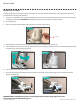
1. Remove the four sideplate screws. Remove sideplates to access the mounting holes. (Figure 1)
2. Remove the two 5/16” e-clips retaining the extension damper. Remove the extension damper to expose the front left
mounting hole. (Figure 2)
3. Place the motor on the bow of the boat. It is recommended that the motor be mounted as close to the centerline of the boat
as possible. Make sure the slot on the underside of the mounting base is aligned with the rubrail of the boat. This will ensure
that the shaft has a minimum clearance of 1-1/2” when it is deployed. (Figure 3 & 4)
4. Once the motor is positioned, mark at minimum, four of the six holes that are located farthest apart (at least two on each
side). Make sure the area under the mounting location is clear to drill holes and install nuts and washers. Drill through the
marked holes using a 5/16” drill bit.
5. Mount the motor to the boat using the provided hardware. Install the hex head bolts and clipped washers on the right side of
the motor as viewed from the boat interior. (Figure 5) Motor can then be slid into place utilizing the slots on the motor base
Parts Included:
Description Qty.
Screw, 1/4-20 x 2” HH SS 6
Screw, 1/4-20 x 0.5 HH SS 6
Washer-Clipped, 1/4”, 1” OD 6
Nut, 1/4-20 Nylock SS 6
Washer, 1/4” Flat 18-8 SS 6
Washer-Mounting, Rubber 6
minnkotamotors.com
©2014 Johnson Outdoors Marine Electronics, Inc.
Tools and Resources Required:
• Drill
• 5/16” Drill Bit
• 7/16” Wrench
• 9/16” Wrench (for prop)
• Wire Ties (for cable routing)
• Phillips Screwdriver
• Flat Blade Screwdriver
Figure 1 Figure 2
Figure 3 Figure 4
5/16” e-clip
Extension Damper
Align Slot with Rubrail
Side Plate
Side Plate Screws
Figure 7
Figure 8Figure 7
minnkotamotors.com | 9
©2015 Johnson Outdoors Marine Electronics, Inc.
InsTALLATIOn