Absolute COLOR® • Absolute BLACK® • Unidrums® • Unirollers® • Uniparts® • Unicoatings® MINOLTA® MAGICOLOR 5430 • 5440 • 5450 CARTRIDGE REMANUFACTURING INSTRUCTIONS MINOLTA® MAGICOLOR 5430 COLOR LASER PRINTER WITH TONER CARTRIDGE w w w. u n i n e t i m a g i n g . c o m / t e c h n i c a l . a s p 11124 Washington Blvd., Culver City, California USA 90232 • Ph +1 310 280 9620 • Fx +1 310 280 0533 • techsupport2@uninetimaging.com © 2007 UniNet Imaging Inc.
UNINET IMAGING INC. • MINOLTA ® MAGICOLOR 5430 CARTRIDGE REMANUFACTURING INSTRUCTIONS MINOLTA® MAGICOLOR 5430 TONER CARTRIDGE SIDE VIEW WITH END CAP SHOWN BACK VIEW OPPOSITE SIDE VIEW w w w. u n i n e t i m a g i n g . c o m / t e c h n i c a l . a s p 11124 Washington Blvd., Culver City, California USA 90232 • Ph +1 310 280 9620 • Fx +1 310 280 0533 • techsupport2@uninetimaging.com © 2007 UniNet Imaging Inc. All Trademark names are property of their respective owners.
UNINET IMAGING INC. • MINOLTA ® MAGICOLOR 5430 CARTRIDGE REMANUFACTURING INSTRUCTIONS SEPARATING THE CARTRIDGE 1. Locate the cartridge end cap of the cartridge. 2. Cartridge separated. Set the drum unit and end cap aside. We will now proceed to clean the toner hopper. Using a phillips screwdriver, remove the seven highlighted screws that hold the cartridge together. CLEANING THE TONER HOPPER 3. Locate the toner hopper fill plug. 4.
UNINET IMAGING INC. • MINOLTA ® MAGICOLOR 5430 CARTRIDGE REMANUFACTURING INSTRUCTIONS SEPARATING THE DRUM UNIT 5. The drum unit (top) and developer unit (bottom) are joined together. 6. Locate the gear train side of the drum unit. Remove the OPC contact (highlighted). Now remove the gear train directly behind it. Note the positioning of the gears. One of the gears is not removable. 7. After removing he gears, release the two screws that hold the drum axle plate in place. 8. Drum axle plate removed.
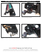
UNINET IMAGING INC. • MINOLTA ® MAGICOLOR 5430 CARTRIDGE REMANUFACTURING INSTRUCTIONS 9. Release the compression spring on the opposite side of the drum unit (drive gear side). Note: The compression springs are different, the longer spring is connected to the gear train side of the drum and the small spring is connected to the drive gear side. 11. Developer roller drive gear removed. 10. Locate the developer roller drive gear just below the OPC.
UNINET IMAGING INC. • MINOLTA ® MAGICOLOR 5430 CARTRIDGE REMANUFACTURING INSTRUCTIONS 13. Separate the two halves by first pulling out the developer unit from where the pin was removed. Once it clears the waste hopper section pull the two halves apart away from each other as shown DISASSEMBLING THE DRUM UNIT 14. Remove the OPC drive gear support by first releasing the screw that holds the support plate in place. 15.
UNINET IMAGING INC. • MINOLTA ® MAGICOLOR 5430 CARTRIDGE REMANUFACTURING INSTRUCTIONS REMOVING THE OPC 17. Once the OPC drive gear support plate has been removed, it will allow movement for the drum axle and will simplify the removal of the OPC. Note: the drum is secured on the axle with pressure. It will take some force to remove. 18. Picture of OPC drum removed. Note: It will not be necessary to remove the drum axle but it can easily removed by angling the axle and pulling it out of its support.
UNINET IMAGING INC. • MINOLTA ® MAGICOLOR 5430 CARTRIDGE REMANUFACTURING INSTRUCTIONS REMOVING THE WIPER BLADE 21. Remove the wiper blade by first disengaging the two screws (shown) that hold it in place. 22. Remove the wiper blade in the manner shown. CLEANING THE WASTE HOPPER 23. Hopper shown with wiper blade completely removed. ASSEMBLING THE DRUM UNIT 24. Install the corona wire assembly via the gear train side first.
UNINET IMAGING INC. • MINOLTA ® MAGICOLOR 5430 CARTRIDGE REMANUFACTURING INSTRUCTIONS 25. Once the corona wire is aligned with the cartridge, Push it with your finger tips until it is back into its original place. INSTALLING THE OPC 26. Before inserting the OPC, make sure its gears are facing in the correct position. 27. Install the OPC drive gear support as shown. 28. Rotate the support clockwise until it locks into place. Once it locks it will need to be secured with its appropriate screw. w w w.
UNINET IMAGING INC. • MINOLTA ® MAGICOLOR 5430 CARTRIDGE REMANUFACTURING INSTRUCTIONS 29. Assemble the two halves by first inserting the drive gear. 30. Once that has been accomplished join the two halves and insert the pin on the gear train side. 31. Install the developer roller drive gear and its appropriate screw. 32. On the opposite side, install the support plate and fasten with two screw as shown. w w w. u n i n e t i m a g i n g . c o m / t e c h n i c a l . a s p 11124 Washington Blvd.
UNINET IMAGING INC. • MINOLTA ® MAGICOLOR 5430 CARTRIDGE REMANUFACTURING INSTRUCTIONS 33. Once the two halves are assembled, continue installing the gear train and springs as shown. BEFORE AFTER REMOVING THE OEM CHIP 34. Locate the OEM chip on the inner portion of the end cap (shown). The chip has been fastened with a minimal amount of pressure and can be removed without tools. ALTERING THE CHIP HOLDER 35.
UNINET IMAGING INC. • MINOLTA ® MAGICOLOR 5430 CARTRIDGE REMANUFACTURING INSTRUCTIONS 36. Aftermarket chip installed. 37. Install the drum contact as shown. ASSEMBLING THE END CAP 38. Once the chip has been installed, you can proceed with installing the inner section of the end cap. 39. Install the transfer tube as shown. w w w. u n i n e t i m a g i n g . c o m / t e c h n i c a l . a s p 11124 Washington Blvd.
UNINET IMAGING INC. • MINOLTA ® MAGICOLOR 5430 CARTRIDGE REMANUFACTURING INSTRUCTIONS 40. Install the outer end cap. 41. Secure the end cap with the seven screws. NOTES w w w. u n i n e t i m a g i n g . c o m / t e c h n i c a l . a s p 11124 Washington Blvd., Culver City, California USA 90232 • Ph +1 310 280 9620 • Fx +1 310 280 0533 • techsupport2@uninetimaging.com © 2007 UniNet Imaging Inc. All Trademark names are property of their respective owners.