0990-7701-02 Color PageWorks User's Manual Copyright 1997 MINOLTA CO., LTD Printed in Japan The information contained in this manual is subject to change without notice to incorporate improvements made on the product or products the manual covers. MINOLTA CO., LTD 3-13, 2-chome, Azuchi-machi, Chuo-ku, Osaka, 541, Japan 7.
i Color PageWorks This manual explains the functions and operation of the MINOLTA Color PageWorks printer. It also gives some troubleshooting tips as well as general precautions to be observed when operating this printer. To ensure the best performance and effective use of your printer, please read this manual carefully from cover to cover. After you have read through the manual, keep it near your printer for handy reference. It should help in solving any operational questions you may have.
ii Safety Information LASER SAFETY This is a page printer which operates by means of a laser. There is no possibility of danger from the laser, provided the printer is operated according to the instructions in this manual provided. Since radiation emitted by the laser is completely confined within protective housing, the laser beam cannot escape from the machine during any phase of user operation. INTERNAL LASER RADIATION (For all Users) Maximum Radiation power: 1.
iii Safety Information USER INSTRUCTIONS (FOR U.S.A. Users) FCC PART 15- RADIO FREQUENCY DEVICES WARNING (Note: Color PageWorks printer without Minolta Network option installed.) WARNING This equipment has been tested and found to comply with the limits for a Class B digital device, pursuant to Part 15 of the FCC Rules. These limits are designed to provide reasonable protection against harmful interference in a residential installation.
iv Safety Information USER INSTRUCTIONS (FOR Canadian Users) INTERFERENCE-CAUSING EQUIPMENT STANDARD (ICES-003 ISSUE 2) WARNING (Note: Color PageWorks printer without Minolta Network option installed.) This Class B digital apparatus meets all requirements of the Canadian Interference-Causing Equipment Regulations. Cet appil numérique de la class B respecte toutes les exigences du Règlement sur le matériel brouilleur du Canada.
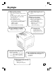
v Highlight 2. Adobe PostScript Level 2 1. High quality printing • Option • Clear text and excellent graphics with true 600 dpi. • Excellent graphics (106 lpi, 122gray levels) • Super Fine Micro Toning (Fine-MT) developing system. • 8µm small particle toner. • Color matching technology. - Apple ColorSync (is available only when the optional Adobe PostScript ROMSIMM is installed). - Windows95 ICM. - Printer embedded color matching. 3. High speed printing • Full color 3ppm, B/W 12ppm.
vi Using This Manual Organization This manual consists of 6 chapters. Chapters 1 and 2 give the basic information about the printer, chapter 3 introduces the menu utilities of the printer operation, chapter 4 through 6 cover maintenance of the printer and some troubleshooting tips. Please read chapter 1 and 2 before attempting to use your printer. Reading these chapters will help you understand the installation and basic operation of your printer.
vii Page Layout Operational Heading Before operation: Gives an overview of the function/ operation covered herein. Page Number: Used to locate your page. Note: Calls your attention to a particular point in the procedure. Continuation marker: Indicates that there is more information to complete an operation on the next page. Index: Used to locate your chapter quickly. Step No.: Sequential number to follow in performing the procedure.
viii CONTENTS Energy Star Information Introduction i Safety Information ii Highlight v Using This Manual vi Contents viii Chapter 1 Installation 1 1. Preparation for Installation 2 Installation Site/ Power Source/ Grounding 2 Space Requirements 3 2. Precautions for Use 4 Operating Environment/ Using the Printer Properly 4 Care of Printer Supplies/ Moving the Printer 5 3.
ix CONTENTS CHAPTER 1 Chapter 3 Changing the Printer Settings 45 Installation 1. List of MENU Utilities 36 2. Setting the MENU Utilities 38 3. Outline of the MENU Utilities 40 Using the Printer ⋅ RESET MENU/ TEST PRINT MENU 40 ⋅ PRINT MENU 41 ⋅ CONFIG MENU 42 ⋅ IMAGE MENU/ MEMORY MENU 43 ⋅ PCL MENU 44 ⋅ PS MENU / MAINTENANCE MENU 45 Chapter 4 Maintaining Your Printer 47 1.
x 7701
For U.S.A./ Canada Users As an ENERGY STAR Partner, MINOLTA Co., Ltd has determined that this printer meets the ENERGY STAR Guidelines for energy efficiency. For Other Country Users This printer meets the *EPA’s ENERGY STAR Guidelines for energy efficiency. *The U. S. Environmental Protection Agency. What is an Energy Star Printer? Energy Star Printers have a feature that allows them to automatically “go to sleep” after a period of inactivity.
Installation This chapter covers site preparation, precautions for use, and set-up procedure. 1. Preparation for Installation 2 Installation Site 2 Power Source 2 Grounding 2 Space Requirements 3 2. Precautions for Use 4 Operating Environment 4 Using the Printer Properly 4 Care of Printer Supplies 5 Moving the Printer 5 3.
Installation CHAPTER 1 2 1. Preparation for Installation Installation Site To ensure a longer life for the printer, it is highly important to select an appropriate installation site. Choose a site that meets the following requirements. - A well-ventilated place. - An area which will not generate ammonia or other organic gas. - A place which is near a power outlet so that the power cord can be easily plugged in and unplugged. - An area free from direct sunlight.
Space Requirements You must provide open space on all sides of the Printer. Allow at least 300mm (11-3/4 inch) of space above the printer as well, so that you can open the printer cover to replace supplies and clear paper misfits. You also will need easy access to the rear of the printer to connect the printer cable and clear paper misfits. 300mm (11-3/4 inch) 300mm (11-3/4 inch) 100mm (4 inch) 1,380mm (54-1/4 inch) 550mm (21-3/4 inch) 905mm (35-3/4 inch) Installation 1.
Installation CHAPTER 1 4 2. Precautions for Use Operating Environment The operating environmental requirements of the printer are as follows. - Temperature: 10°C (50°F) to 35°C (86°F) with a fluctuation of 10°C (50°F) per hour. - Humidity: 15% to 85% RH with a fluctuation of 20% per hour. * The environmental zone marked “X” on the right represents a critical environment in which the printer can be left to stand.
NOTE NOTE = Locate the printer in a Well Ventilated Room = A negligible amount of ozone is generated during normal operation of this printer. An unpleasant odor may, however, be created in poorly ventilated rooms during extensive printer operations. For a comfortable, healthy, and safe operating environment, it is recommended that the room be well ventilated.
3. Setting-Up - The following four different procedures must be performed to set up the printer. Perform them step by step. 1. Hardware Setting-Up (Printer and 250-Sheet Third Cassette Unit) ☞Unpacking/ Setting-Up Instructions*1 2. Checking Print Operation ☞p. 6 3. Connecting Printer to Host Computer ☞p. 8 4.
5 - Press the On Line key on the control panel. - Check that “OFF LINE” appears on the Message Display. - Check that the On Line Indicator goes out. 9 - Check that the data on the following demonstration page is printed. Typical Printout: ✕ Once OFFLINE 6 - Press the Menu key on the control panel twice. - Check that “TEST PRINT MENU” appears on the Message Display.
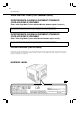
3. Setting-Up Connecting Printer to Host Computer Installation CHAPTER 1 8 PRECAUTION - This printer is equipped with the following two types of interface connectors for connection to the host computer. Select the correct interface to suit the host computer to be used. Parallel interface - Connector type: IEEE 1284 36-pin Amphenol (full) - Typical compatible computer models: IBM PC/AT or compatible (OS: Windows 3.1/3.
3 For Serial Interface - Connect one end of the interface cable to the serial port of the host computer. - Connect the other end of the interface cable to the interface connector on the back side of the printer. Serial Interface connector Interface cable 4 - This completes the connection of the printer to the host computer. - You next install the printer driver (software).
3. Setting-Up Expansion Memory (Option) Setting-Up Installation CHAPTER 1 10 PRECAUTION - This printer is equipped with two sockets for the installation of expansion memory. - The optional expansion memories come in five different capacities: 1 MB, 2 MB, 4 MB, 8MB, 16 MB, and 32 MB. The combination in which expansion memories of different capacities are plugged in allows the memory capacity of the printer to be expanded up to 68 MB (standard 4 MB + expansion 64 MB).
in your printer. - Mount the expansion memory in the socket (SIMM3 or 4) at the location shown on the controller board. SIMM3 9 CHAPTER 1 5 - Take the Expansion Memory out of its carton. - Check which type of Controller board is installed 3. Setting-Up -Insert the controller board into the guide rails. - Secure the controller board in position with the Installation 11 four screws. SIMM4 Controller board (a) SIMM3 SIMM4 Controller board (b) 6 - Insert the expansion memory pin into the socket.
3. Setting-Up Adobe PostScript ROM SIMM (Option) Setting-Up Installation CHAPTER 1 12 PRECAUTION - This printer is equipped with a socket for the installation of an Adobe PostScript ROM SIMM. When the printer is equipped with an Adobe PostScript ROM SIMM, it can function as a PostScript printer. CAUTION - Before opening the optional packages or handling the options, briefly touch the metal part of the printer to remove any electrostatic charge from your body.
in your printer. - Mount the PostScript ROM in the socket (SIMM2) at the location shown on the controller board. SIMM2 9 CHAPTER 1 5 - Take the PostScript ROM out of its carton. - Check which type of Controller board is installed 3. Setting-Up - Insert the controller board into the guide rails. - Secure the controller board in position with the Installation 13 four screws. Controller board (a) SIMM2 Controller board (b) 6 - Insert the PostScript ROM pin into the socket.
3. Setting-Up Network Board (Option) Setting-Up Installation CHAPTER 1 14 PRECAUTION - The network board is equipped with the following two types of interface connectors for connection to the network server. Select the correct interface to suit the network to be used. 10BASE-T 10BASE-2 3. Setting-Up Expansion Memory Setting- - The type of cable used for connecting the printer to the network server varies depending on the connection method of the network to be used.
5 - Insert the network board into the mounting rails. 6 - This completes the procedure to mount the - Tighten the two screws that secure the network board in position. network board in the printer. - Now, read the Network Printer Operator's Manual separately provided (that is shipped together with the accessories that come with the Network Board set), connect the network cable and set the network environment variable through the host computer.
Installation CHAPTER 1 16 3.
17 Chapter 2 This chapter gives basic information on the different parts of the printer and shows you how to use the printer. 1. Printer Parts and Accessories 18 ⋅ Printer 18 ⋅ Accessories 19 ⋅ Control Panel keys 20 ⋅ Operation and Warning Labels 22 2. Turning ON and OFF the Printer 23 3. Printing Paper 24 ⋅ Type 24 ⋅ Size 24 ⋅ Capacity 24 ⋅ Print Area 25 ⋅ Care of paper 25 4.
18 1. Printer Parts and Accessories Power Switch Print Tray The printed paper is fed out face down onto this tray. The tray can hold 250 sheets of printed paper. ☞p. 34 Using the Printer CHAPTER 2 PRINTER Use to turn the printer ON and OFF ☞p. 23 Front Cover Swing open to change supplies such as the Toner Cartridge or to clear a paper misfeed. Control Panel -Allows the operator to make various settings. -The LCD Display shows the current status of the printer.
19 1. Printer Parts and Accessories Toner Cartridge Waste bottle - Used to collect and contain waste toner. - Replace this Bottle with a new one when it is filled with waste toner. - Put the old bottle in a polyethylene bag or the like and dispose of it according to your local regulations. ☞p. 56 - There are four different color Toner Cartridges: Black, Yellow, Magenta and Cyan. - Replace this cartridge with a new one when it runs out of toner.
20 1. Printer Parts and Accessories Using the Printer CHAPTER 2 CONTROL PANEL KEYS Message Display - Shows the message telling the current status Data Indicator of the printer. - Shows the setting made for the various functions. - Data Indicator ON When data received from the host computer is stored in the printer memory. - Data Indicator OFF When no data is stored in the printer memory, usually immediately after power on or reset.
21 1. Printer Parts and Accessories Menu Key ☞p. 38 Item Key Accesses the list of items after selecting a Menu and selects the menu item. This key must be pressed when Menu is selected otherwise no action takes place while displaying “Off Line”. The items go through a loop until the On Line key is pressed or the Menu key is pressed. When the On Line key is pressed, the printer returns to On Line and when the Menu key is pressed, the next Menu selection is displayed. ☞p.
22 1. Printer Parts and Accessories Using the Printer CHAPTER 2 OPERATION AND WARNING LABELS Installing the Toner Cartridge - Describes how to replace the Toner Cartridge when it runs out of toner. For details of operation, refer to “Changing the Toner Cartridge” on page 48. Changing the Waste bottle, Drum Cartridge and Oiling Roller - Describes how to replace the Waste bottle, Drum Cartridge and Oiling Roller.
23 Turning Printer Printer ON ON Turning Press the Power Switch to the ❙ (ON) position. Turning Printer OFF Turning Printer OFF Press the Power Switch to the (OFF) position. WhenPrinter PrinterisisTurned TurnedON ON When The printer will be ready to make a print approx. 90 sec. after the Power Switch is turned ON. NOTE NOTE - If no print commands are sent from the host computer to the printer for 15 min., the printer automatically enters standby in the Power save mode.
L 24 Using the Printer CHAPTER 2 3. Printing Paper PRECAUTION This printer is designed to print the following types of paper. Any other types of paper must not be used. Type *: Does not support Legal L size Thick Paper. Paper Feeding Port Plain Paper weighing: 60 to 90 g/m2 16 to 24 lbs. Special Paper Recycled Paper weighing: 60 to 90 g/m2 16 to 24 lbs. OHP Sheet Labels Letterhead JPost(Postcard) size: 100 ✕ 148 mm 4" ✕ 5-3/4” Envelopes Thick Paper* weighing: 90 to 157 g/m2 24 to 41-1/4 lbs.
25 3. Printing Paper 4mm (0.16") 4mm (0.16") 4mm (0.16") Printable area 4mm (0.16") For full-color printing 293mm (11-1/2”) For monochrome printing 352mm (13-3/4”) - Monochrome (black) printing can be done on paper up to 352mm (13-3/4”) in length, with the exception of four 4mm (0.16") margins. - Full color printing can be done on paper up to 293mm (11-1/2”) in length, with the exception of four 4mm (0.16") margins. Care of Paper Use the following precautions when handling the paper.
26 4. Loading the Printing Paper CHAPTER 2 Loading Plain Paper / Recycled Paper PRECAUTIONS Using the Printer ⋅ Do not use the following paper. To do so will lead to reduced print quality, a misfeed or a failure. - Paper already used in a thermal transfer printer or ink jet printer. - Paper that is too thin (under 60 g/m 2, 16 lbs.) or too thick (over 157 g/m2, 41-1/4 lbs.). - Paper folded, curled or broken. - Paper having binding holes or perforations.
27 4. Loading the Printing Paper 1 - Slide out the TRAY 2 (second Cassette) or TRAY 3 (Third Cassette). 5 -Pressing the Guide Lock Lever, adjust the Paper Guides to fit the size of the Paper. Paper Guides Guide Lock Lever 2 - Press down the Paper Lifting Plate until it locks. 6 - Set the Paper Size Indicator to fit the size of the paper used. A4 Legal Letter 2 3 Paper Size Indicator - Install the Trailing Edge Guide to fit the size of the paper to be loaded.
28 4. Loading the Printing Paper 9 - Fan the paper stack thoroughly and align its edges. 12 - Slide in the Cassette. Using the Printer CHAPTER 2 TRAY 2 (Second Cassette) / TRAY 3 (Third Cassette: option) 10 - Load the paper stack in the Cassette facing down, its corners are under the Paper Separator and its leading edge makes contact with the front side of the Cassette. Face down Paper Separator Π2 11 NOTE - The paper should be loaded no higher than the Max. Level Indicator.
29 4. Loading the Printing Paper PRECAUTIONS ⋅ Labels must be loaded in the TRAY 1 (Multi Purpose Tray). Do not load them in the TRAY 2 (Second) / TRAY 3 (Third Cassette). ⋅ When handling OHP sheets, it is recommended to wear gloves so that they are not soiled with fingerprints and smears. Soiled OHP sheets may lead to a defective printed image. ⋅ Do not use the following paper. To do so may lead to reduced print quality, a misfeed or a failure. - Labels which are easy to peel.
30 4. Loading the Printing Paper 1 - Slide out the TRAY 2 (second Cassette) or TRAY 3 (Third Cassette). 5 -Pressing the Paper Guide Lock Lever, adjust the Paper Guides to fit the size of the Paper. Paper Guides Using the Printer CHAPTER 2 TRAY 2 (Second Cassette) / TRAY 3 (Third Cassette: option) Guide Lock Lever 2 - Press down the Paper Lifting Plate until it locks. 6 - Set the Paper Size Indicator to fit the size of the paper used.
31 4. Loading the Printing Paper 9 - Load the standard OHP stack in the Cassette facing down, its corners are under the Paper Separator, and its leading edge makes contact with the front side of the Cassette. 2 11 Paper Separator NOTE - When you want to replenish the OHP, take out the remaining OHP and stack them on the additional OHP. Then fan the OHP and load them. - We recommend replenishing the OHP only when the Cassette is empty. Face down 10 NOTE - Load the recommended OHP (Minolta CF-200 (D).
32 4. Loading the Printing Paper Using the Printer CHAPTER 2 Loading Special Paper (Letterhead/ Envelopes/ Postcard/ Thick Paper) Œ PRECAUTIONS ⋅ Do not use Legal L size Thick paper. (Does not support Legal L size Thick Paper.) ⋅ Do not use the following paper. To do so will lead to reduced print quality, a misfeed or a failure. - Paper already used in a thermal transfer printer or ink jet printer. - Paper that is too thin (under 60g/m2, 16 lbs.) or too thick (over 90g/m2, 24 lbs.).
33 4. Loading the Printing Paper 5 - When printing Envelopes, fold their flaps securely and load them on the Tray with their flap side down. 9 Face up - When printing Letterhead, load it on the Tray with the Header end at the take-up end. 6 7 8 NOTE - Generally, envelopes perform well, but some types may wrinkle. We strongly recommend testing any type of envelopes before buying it in large amounts. - When printing paper, load it on the Tray after straightening warped paper, if any.
34 5. Printing Paper can be fed for printing either from the TRAY 1 (Multi Purpose Tray), the TRAY 2 (Second Cassette) or the TRAY 2 (Third 1 - Turn the printer on. “Turning ON and OFF the Printer” ☞p. 23 4 - Input a print command from the host computer. The printed paper is fed out onto the Print Tray with the image face down. Using the Printer CHAPTER 2 ŒCassette optional). As available paper depends on the paper port, use the paper port that suits your application.
35 Chapter 3 Changing the Printer Settings ⋅ RESET MENU 40 - JOB & MEMORY/ MENU RESET ⋅ TEST PRINT MENU 40 - PRINT CONFIG/ PCL FONT LIST/ PS FONT LIST / PCL DEMO PAGE/ PS DEMO PAGE ⋅ PRINT MENU 41 - COPIES/ TRAY1 PAPER/ MANUAL FEED/ TRAY SWITCHING/ PAPER SOURCE/ PAPER SIZE/ TRAY1 MEDIA/ TRAY2 MEDIA/ TRAY3 MEDIA/ ORIENTATION/ FORM LENGTH ⋅ CONFIG MENU 42 - PERSONALITY/ AUTO CONTINUE/ I/O TIMEOUT/ POWER SAVE/ DISPLAY LANGUAGE ⋅ IMAGE MENU 43 - PRINT MODE ⋅ MEMORY MENU 43 - PCL CONTEXT SAVE/ PS CONTEXT SAVE
36 1. List of MENU Utilities The MENU utilities refer to the functions which have settings you can change to suit your particular operating needs. There are a total of 34 features available in the MENU utilities, classified under Nine major groups as detailed below. Changing the Printer Settings CHAPTER 3 MENU 1. RESET MENU 2. TEST PRINT MENU 3. PRINT MENU 4. CONFIG MENU ITEM SETTING 1. JOB & MEMORY ENTER to reset. 2. MENU RESET ENTER to reset. 1. PRINT CONFIG ENTER to print. 2.
37 1. List of MENU Utilities SETTING 5. IMAGE MENU 1. PRINT MODE FULL COLOR/ MONOCHROME 6. MEMORY MENU *5 1. PCL CONTEXT SAVE OFF/ ON 2. PS CONTEXT SAVE OFF/ ON 1. FONT SOURCE INTERNAL / SOFT FONT 2. FONT NUMBER INTERNAL: 0 to 52 (SOFT FONT: 0 to max. 999) 3. FONT PITCH 0.44 to 99.99 (10.00 ) 4. FONT POINT SIZE 4.00 to 999.75 (12.00 ) 5. SYMBOL SET *3 8. PS MENU *1 1. PRINT PS ERROR OFF/ ON 9. MAINTENANCE MENU 1. TOTAL PRINT OUTS 7. PCL MENU 2.
38 2. Setting the MENU Utilities 1 - Make sure that "READY" is shown on the Message Display and the On Line Indicator is lit. 4 Example: Print Menu ✕ 3 times RAEDY Changing the Printer Settings CHAPTER 3 READY PRINT MENU 2 - Press the On Line key on the control panel. - Check that "OFF LINE" appears on the Message 5 Display. - Make sure that the On Line Indicator goes out. - Press the Item key on the control panel as many times as is necessary to select the desired item.
39 2. Setting the MENU Utilities 8 - Press the On Line key on the control panel. - Check that "ON LINE" appears on the Message Display. ✕ Once CHAPTER 3 - Make sure that the On Line Indicator lights up. - This completes the setting procedure of the MENU utilities. 9 NOTE - To quit the MENU function (while you are in any step from step 3 through 6), press the On Line key. Pressing the On Line key cancels the MENU function and returns to the On Line mode.
40 3. Outline of the MENU Utilities 1. RESET MENU RESET MENU is a group that provides the JOB & MEMORY and MENU RESET. The user may reset the parameters of the printer. Changing the Printer Settings CHAPTER 3 1. JOB & MEMORY JOB & MEMORY will reset the printer when the Enter key is pressed, clearing all stored page data from memory. The printer resumes on-line. 2. MENU RESET - MENU RESET will reset the printer when the Enter key is pressed. The printer settings are reset to the Factory Defaults.
41 3. Outline of the MENU Utilities 3. PRINT MENU PRINT MENU is a group of menu selections which is used frequently. It includes COPIES, PAPER SIZE and ORIENTATION and so on. 2. TRAY1 PAPER - The paper size of the TRAY 1 (Multi Purpose Tray) is selected. - The settings are A4, A5, Letter, Invoice, JIS-B5, Legal, Executive, COM 10, C5, DL, Monarch, and J-Post. - European models have A4 as the default whereas U.S. and other North American models have Letter as the factory default. 3.
42 3. Outline of the MENU Utilities 3. PRINT MENU CHAPTER 3 9. TRAY3 MEDIA - The TRAY 3 (Third Cassette) media type is selected. The factory default media type is PLAIN PAPER. - When TRANSPARENCY and FULL COLOR (PRINT MODE ☞p. 43) are both selected, the engine slows the machine throughput to one-third so that it can saturate the toner application. - When THICK PAPER is selected, the engine slows the machine throughput to one-third so that it can saturate the toner application.
43 3. Outline of the MENU Utilities 4. CONFIG MENU 5. DISPLAY LANGUAGE - The default language of the panel is selected. 5. IMAGE MENU CHAPTER 3 - There are currently 5 languages. The settings are ENGLISH, DEUTSCH, FRANCAIS, ITALIANO and NEDERLANDS. - The factory default is ENGLISH. 1. PRINT MODE - The type of printed image is selected (full color, monochrome). - When FULL COLOR and TRANSPARENCY (TRAY 1, 2, 3 MEDIA ☞pp.
44 3. Outline of the MENU Utilities 7. PCL MENU PCL MENU is a group of menu selections which is used frequently. Changing the Printer Settings CHAPTER 3 1. FONT SOURCE - The font source is selected (Internal fonts, Soft fonts). - The printer’s internal memory (INTERNAL) provides a major source for the fonts that can be selected. - The SOFT FONT setting refers to down loaded font. - The factory default setting is INTERNAL. 2. FONT NUMBER - The default font number to be used is selected.
45 3. Outline of the MENU Utilities Understanding Fonts Bitmap Fonts A bitmap font is stored in printer memory as a set of characters and symbols with a specific size and unique design. Each bit of the font is precisely mapped, so this type of font cannot be scaled to different sizes. This printer maintains 10 TrueType fonts and 35 Intellifont typefaces in memory. Soft Font A soft font is downloaded from host computer to printer memory when it is required.
Changing the Printer Settings CHAPTER 3 46 3.
47 Chapter 4 Maintaining Your Printer This chapter covers the procedures to be used for adding and changing supplies and maintaining your printer. 2. Cleaning the Printer 70 Maintaining Your Printer ⋅ Changing the Toner Cartridge 48 Auto Mode 48 Manual Mode 52 ⋅ Changing the Drum Cartridge, Waste Bottle and Oiling Roller 56 ⋅ Changing the Fusing Unit and Transfer Roller Unit 62 ⋅ Changing the Image Transfer Belt Unit 66 CHAPTER 4 1.
48 1. Changing Cartridges Maintaining Your Printer CHAPTER 4 Œ Changing the Toner Cartridge ⋅ There are four Color Toner Cartridges: Black, Yellow, Magenta and Cyan. When any of the Color Toner Cartridges run out of toner, change it for a new one. ⋅ When any Color Toner Cartridge runs short of toner, “TONER LOW” is displayed to indicate that it will run out of toner soon. In this case, remove the corresponding Cartridge, shake it several times, and reload it into the printer.
49 1. Changing Cartridges 5 Example: Color Toner Cartridge Magenta (Red) 8 - Grasp and pull down the Front Cover Lock Release Lever to swing open the Front Cover ✕ Twice Front Cover Lock Release Lever - Press the Enter key on the control panel. 9 -Hold the handle of the used Toner Cartridge and pull it toward you. - Check that “PLEASE WAIT XXXXX” appears on the Message Display. - You will hear the sound of the printer operating. - The Message Indicator starts blinking.
50 1. Changing Cartridges 12 NOTE - Never touch the roller in the Toner Cartridge. Print quality will be reduced. 15 - Hold the new Cartridge in the position shown and insert the green pin on the right side of the Cartridge into the green installation guide of the Rack. Green pin Maintaining Your Printer CHAPTER 4 Roller 13 - Make sure that the toner color label of the Toner°Cartridge Rack is the same color as that of the Toner Cartridge.
51 1. Changing Cartridges 17 - Firmly press the Cartridge into the Rack. - The Cartridge clicks into place when it is installed correctly. 20 - Make sure that the sound of the printer operation has died away, indicating that the printer is stationary. - Check that “REPLACE TONER XXXXXXX. - Make sure that the Message Indicator lights off. Example: Color Toner Cartridge Magenta (Red) - PUSH DOWN ONLY ON THE GREEN SQUARES on the top face of the Drum Cartridge.
52 1. Changing Cartridges Changing the Toner Cartridge ΠManual mode 1 - Grasp and pull down the Front Cover Lock Release Lever to swing open the Front Cover 3 - To confirm the Rack position for removing the Cartridge, use the position confirmation window beside the Dial. The removal position indicator appears in the window to show that the Rack is in position for the Cartridge.
53 7 - Remove a new Toner Cartridge from its carton and, holding the cartridge as shown, shake it well. 10 - When installing the Cartridge, hold the Rack Dial with your left hand to prevent the Rack from turning. 11 - Hold the new Cartridge in the position as shown and insert the green pin on the right-hand side of the Cartridge into the green installation guide of the Rack. Green pin 2 8 NOTE - Never touch the roller in the Toner Cartridge. Print quality will be reduced.
54 1. Changing Cartridges 13 - Firmly press the Cartridge into the Rack. - The Cartridge clicks into place when it is installed correctly. 16 - Make sure that the sound of the printer operation has died away, indicating that the printer is stationary. - Check that “READY” appears on the Message Display. Maintaining Your Printer CHAPTER 4 READY 14 - PUSH DOWN ONLY ON THE GREEN SQUARES on the top face of the Drum Cartridge. - The Cartridge clicks into place when it is installed correctly.
Maintaining Your Printer CHAPTER 4 55 1.
56 1. Changing Cartridges Changing the Drum Cartridge, Waste Bottle and Oiling Roller ⋅ The Drum Cartridge provides A4/letter-size prints of up to about 20,000 images. One image is equal to one cycle of Drum Cartridge operation. The Drum Cartridge operates once (one image) to provide one monochrome print. In comparison, the Drum Cartridge operates four times (four images) to provide one color print. ⋅ When 20,000 images are calculated in terms of color prints, about 5,000 sheets can be printed.
57 8 9 10 14 7 - PUSH DOWN ONLY ON THE GREEN SQUARES on the top face of the Drum Cartridge. - The Cartridge clicks into place when it is installed correctly. 11 NOTE - DO NOT PUSH ON the Drum Cartridge Shutter when installing the Drum Cartridge. Doing so may damage the Drum Cartidge. - Remove the old Waste Bottle from the printer. - Remove the Bottle Cap on the old Toner Collecting Bottle and fit it to the mouth of that Bottle to prevent waste toner from falling out.
58 1. Changing Cartridges 12 - Install the Waste Bottle by inserting its guide into the printer's rail. 15 NOTE - Make sure that the Shutter at the toner exit of the Image Transfer Belt Unit is open securely. To start printing with the Shutter closed will lead to internal contamination, a decline in print quality and/ or a failure.
59 1. Changing Cartridges 19 NOTE - The Fusing Unit is hot. Be careful not to touch the area carrying the WARNING! HIGH TEMPERATURE label. - Before changing the Oiling Roller, wait until the surface temperature of the Fusing Unit falls and make sure that the temperature is safe for replacement. 22 - Remove a new Oiling Roller from its carton. - Insert the front end of the guide on the new Oiling Roller into the installation hole of the Fusing Unit to install the Oiling Roller.
60 1. Changing Cartridges 2 26 - Make sure that the button of the Fusing Unit Lock Release Lever is pushed up as shown. OK (LOCKED) 27 - Close the Rear Cover. - The Rear Cover will click when it is closed correctly. Maintaining Your Printer CHAPTER 4 NG (UNLOCKED) Π2 28 - Make sure that the Rear Cover Lock Release Lever is pushed up as shown.
Maintaining Your Printer CHAPTER 4 61 1.
62 1. Changing Cartridges Changing the Fusing Unit and Image Transfer Roller Unit ⋅ The Image Transfer Roller Unit and Fusing Unit can provide up to about 100,000 A4/ letter-size prints. (This value will vary with the color-to-monochrome print ratio, image conditions, etc.) ⋅ Change the Fusing Unit and Image Transfer Roller Unit at the same time.
63 8 - PUSH DOWN ONLY ON THE GREEN SQUARES on the top face of the Drum Cartridge. - The Cartridge clicks into place when it is installed correctly. 11 12 - Push and hold the button of the Fusing Unit Lock Release Lever and slide out the Fusing Unit. NOTE - The Fusing Unit is hot. Be careful not to touch the area carrying the WARNING! HIGH TEMPERATURE label. - Before changing the Fusing Unit, wait until its surface temperature falls and make sure that the temperature is safe for replacement.
64 15 - Remove a new Fusing Unit from its carton. 16 - Insert the guide of the Fusing Unit mount into the installation hole of the new Fusing Unit as shown. Maintaining Your Printer CHAPTER 4 1. Changing Cartridges 19 - Turn the Misfeed Clearing Dial of the Fusing Unit counterclockwise and make sure that the white gear shown rotates smoothly. 20 - Hold the Lock Release Lever and push the Fusing Unit in. - The Fusing Unit will click into place when it is installed correctly.
65 1. Changing Cartridges NG (UNLOCKED) CHAPTER 4 OK (LOCKED) Maintaining Your Printer 23 - Make sure that the button of the Rear Cover Lock Release Lever is pushed up as shown.
66 1. Changing Cartridges Changing the Image Transfer Belt Unit. ⋅ The Image Transfer Belt Unit provides A4/letter-size prints of up to about 150,000 images. One image is equal to one cycle of Image Transfer Belt Unit operation. The Image Transfer Belt Unit operates once (one image) to provide one monochrome print. In comparison, the Image Transfer Belt Unit operates four times (four images) to provide one color print.
67 1. Changing Cartridges 8 -Turn the belt fixing bracket on the left side of the Image Transfer Belt Unit to the position shown to unlock the bracket. 11 12 -Pull out the belt fixing bracket. - Install the Image Transfer Belt Unit in the printer, aligning its protrusions with the slots inside the printer frame. Left side grip LOCK Right side grip OPEN 0990U161 9 -Pull out the belt fixing bracket. 13 10 NOTE - When installing the Image Transfer Belt Unit, be sure to hold onto the grips.
68 1. Changing Cartridges 17 14 Green Label Maintaining Your Printer CHAPTER 4 Printer’s rail Œ 15 - Check that the connector from the Image Transfer Belt Unit is positively connected to the connector on the printer end. 18 - Press down on the top face of the Waste Bottle. - The Bottle clicks into place when it is installed correctly. - Make sure that the Hook of the Waste Bottle is engaged securely with the pins of the Image Transfer Belt Unit.
69 1. Changing Cartridges 22 - PUSH DOWN ONLY ON THE GREEN SQUARES on the top face of the Drum Cartridge. - The Cartridge clicks when it is installed correctly. CHAPTER 4 20 NOTE - DO NOT GRASP the Drum Cartridge Shutter when installing the Drum Cartridge. Doing so may damage the Transfer Belt Unit. 23 24 NOTE - DO NOT PUSH ON the Drum Cartridge Shutter when installing the Drum Cartridge. Doing so may damage the Drum Cartridge. - Gently close the Front Cover.
70 2. Cleaning the Printer Dust, dirt, and paper dust on the surfaces and inside the printer can interfere with proper printer perŒformance and quality. Clean the printer at regular intervals. NOTE - Before starting the cleaning procedure, be sure to turn OFF the Power Switch and unplug the power cord from the outlet. - Use a soft cloth for cleaning. Do not use abrasives or corrosive detergent.
71 2. Cleaning the Printer 5 NOTE - Do not touch the surface of the Image Transfer Roller. It may lead to reduced print quality. 2 8 - Gently close the Front Cover. Do not close it violently, because a printer breakdown could result. - You will hear the sound of the printer operating. 6 - Push down the Misfeed Clearing Lever. 7 - Press down on the green labels on the top face of the Drum Cartridge. - The Cartridge clicks into place when it is installed correctly.
Maintaining Your Printer CHAPTER 4 72 2.
73 Chapter 5 Troubleshooting This chapter gives you some troubleshooting tips together with the recommended corrective procedures to follow. 1. How to Troubleshoot 74 2. A Problem Exists in the preparation stage and during a Print Cycle 75 − A Problem Exists in the Preparation Stage 75 − A Problem Occurs When You Attempt to Start a Print Cycle 75 − When a Message Appears 76 − When a Paper Misfeed has Occurred 80 Troubleshooting CHAPTER 5 3.
74 1. How to Troubleshoot When your printer does not operate as you expect it to or when you are not sure about what you should do in mid-operation, make the following checks before calling your Technical Representative. A simple troubleshooting procedure may solve the problem. If the problem persists even after these procedures, then contact your Technical Representative. Diagnosing Your Printer Different steps of action should be taken for different trouble symptoms.
2. A Problem Exists in the Preparation Stage 75 and During a Print Cycle A Problem Exists in the Preparation Stage. Symptom The printer power is not turned ON. Cause Action The power cord is unplugged or loose. Plug the power cord into the printer and outlet. The power outlet may be faulty. Plug another electrical appliance into the outlet to see if it works properly. The LCD shows nothing and The rated voltage of the printer does not the printer makes no sound match the power outlet voltage.
76 2. A Problem Exists in the Preparation Stage and During a Print Cycle When a Message Appears Troubleshooting CHAPTER 5 LCD Message Description Action WARMING UP The Printer is warming up. Wait for a short while. OFF LINE Printer cannot receive data from Host computer. Press the On Line key to set the printer into the On Line state. PROCESSING - Receiving data from the host computer. - The printer is making a print image. Wait for a while.
77 2. A Problem Exists in the Preparation Stage and During a Print Cycle Action REMOVED XXXXX TONER The toner cartridge isn’t present. Mount the Toner Cartridge. ☞p. 48 REMOVED DRUM UNIT The drum cartridge is missing. Mount the Drum Cartridge. ☞p. 56 REMOVED WASTE BOTTLE The waste toner bottle is missing. Mount the Waste Bottle. ☞p. 56 REMOVED OILING ROLLER The Oiling Roller or fusing unit is missing. Mount the Oiling Roller. ☞p.
78 2. A Problem Exists in the Preparation Stage and During a Print Cycle Troubleshooting CHAPTER 5 LCD Message Description Action INTERFACE ERROR PARALLEL PORT An error occurred at the parallel port. INTERFACE ERROR LOCALTALK PORT An error occurred at the localTalk port. INTERFACE ERROR NETWORK An error occurred at the network interface. INSUFFICIENT RAM NEED MORE RAM The RAM size is insufficient. Install an optional Expansion Memory.
79 Troubleshooting CHAPTER 5 2.
80 2. A Problem Exists in the Preparation Stage and During a Print Cycle CHAPTER 2 When a Paper Misfeed has Occurred When a paper misfeed occurs in the printer, remove the paper according to the following procedure. ATTENTION The Fusing Unit inside the Rear Cover can become very hot during operation. Do not touch the area as it may cause a burn. 1 - Pull out the paper misfed in the Paper Exit Port toward you.
81 2. A Problem Exists in the Preparation Stage and During a Print Cycle 12 8 - Make sure that the button of the Rear Cover Lock Release Lever is pushed up as shown. - Lift the Misfeed Clearing Guide of the Fusing Unit and pull out the paper misfed in the Fusing Unit. OK (LOCKED) NG (UNLOCKED) Misfeed Clearing Guide 13 9 - Hold the Lock Release Lever Button and push the Fusing Unit in. - The Fusing Unit will click into place when it is installed correctly.
82 2. A Problem Exists in the Preparation Stage and During a Print Cycle 15 - Pull out the paper misfed in the rollers toward the back side. Troubleshooting CHAPTER 5 16 - Lift the Misfeed Clearing Lever. 19 - Lift the Misfeed Clearing Guide. 20 - Pull out the paper misfed in the rollers toward the top. Π17 NOTE 21 - Close the Misfeed Clearing Guide. 22 - PUSH DOWN ONLY ON THE GREEN SQUARES on the top face of the Drum Cartridge.
83 2. A Problem Exists in the Preparation Stage and During Print Cycle 1. When a Paper Misfeedahas Occurred - Gently close the Front Cover. 27 2 - Slide out the Third Cassette (option). 24 - Slide out the Second Cassette. 28 - Pull out the paper misfed in the Paper Path toward the front. 2 29 - Slide in the Third Cassette. 25 - Pull out the paper misfed in the paper path toward the front. 23 Do not close it violently, because a printer breakdown could result.
84 3. Print Results are Faulty Symptom Light image Cause The print density setting on the host computer is not proper. The paper loaded in the tray is damp. Action Change the print density setting on the host computer to the print density required. Replace the old paper with fresh dry paper. ☞p. 26 The Toner Cartridge is running out of toner. Remove the Toner Cartridge and shake it several times.☞p. 48 Replace the Toner Cartridge with a new one. Troubleshooting CHAPTER 5 ☞p.
85 3. Print Results are Faulty White lines Toner in the cartridge is not even. Remove the Toner Cartridge and shake it several times. ☞p. 48 The Drum Cartridge may be defective. Remove and check the Cartridge for damage. Install a new Cartridge if needed ☞p. 56 The Image Transfer Roller Unit has reached its replacement time. Change the Image Transfer Roller Unit. ☞p. 62 The Toner Cartridge may be defective. Remove and check the Cartridge for damage. Install a new Cartridge if needed.
86 3. Print Results are Faulty Symptom Black pages Cause The Toner Cartridge may be defective. Action Remove and check the Cartridge for damage. Install a new Cartridge if needed. - The Toner Cartridge ☞p. 48 - The Drum Cartridge ☞p. 56 The Drum Cartridge may be defective. Blank pages The Drum Cartridge may be defective. The Image Transfer Roller Unit may be defective. Troubleshooting CHAPTER 5 The Image Transfer Roller Unit may be defective. A paper wrinkle occurs.
87 Chapter 6 Appendices Appendices CHAPTER 6 1. Quick Reference Guide of MENU 88 2. List of MENU Utilities 90 3. Specifications of Printer 92 4. Specifications of 250-sheet Third Cassette Unit 95 5.
88 1.
89 1. Quick Reference Guide of MENU PS MENU *1 MAINTENANCE MENU PCL CONTEXT SAVE FONT SOURCE PRINT PS ERROR TOTAL PRINT OUTS PS CONTEXT SAVE FONT NUMBER REPLACE TONER ➜ FONT PITCH CHAPTER 6 PCL MENU FONT POINT SIZE SYMBOL SET NOTES *1: The range of items to choose from when the printer is equipped with an Adobe Postscript ROM SIMM. *2: The range of items to choose from when the printer is equipped with a 250-sheet Third Cassette Unit.
90 2. List of MENU Utilities MENU 1. RESET MENU 2. TEST PRINT MENU Appendices CHAPTER 6 3. PRINT MENU 4. CONFIG MENU ITEM SETTING 1. JOB & MEMORY ENTER to reset. 2. MENU RESET ENTER to reset. 1. PRINT CONFIG ENTER to print. 2. PCL FONT LIST ENTER to print. 3. PS FONT LIST *1 ENTER to print. 4. PCL DEMO PAGE ENTER to print. 5. PS DEMO PAGE *1 ENTER to print. 1. COPIES 1 to 999 2. TRAY 1 PAPER *2 3. MANUAL FEED OFF / ON 4. TRAY SWITCHING ON / OFF 5.
91 2. List of MENU Utilities SETTING 5. IMAGE MENU 1. PRINT MODE FULL COLOR/ MONOCHROME 6. MEMORY MENU *5 1. PCL CONTEXT SAVE OFF/ ON 2. PS CONTEXT SAVE OFF/ ON 1. FONT SOURCE INTERNAL / SOFT FONT 2. FONT NUMBER INTERNAL: 0 to 52 (SOFT FONT: 0 to MAX. 999) 3. FONT PITCH 0.44 to 99.99 (10.00) 4. FONTPOINT SIZE 4.00 to 999.75 (12.00) 5.
92 3. Specifications of Printer Type Printing system Exposure system Print density Paper Feeding system Paper size : Desktop Full Color Laser Beam Printer : Electrostatic dry powdered imaging system : Laser Diode and Polygon Mirror scanning : 600 dpi (dot/ inch) : 2-way system (TRAY 1: Multi Purpose Tray, TRAY 2: 250-sheet Second Cassette) : Standard size A4, A5, JIS B5, Letter 8-1/2” × 11”, Legal 8-1/2” × 14”, Executive 7-1/4”× 10-1/2” Invoice 8-1/2” × 5-1/2” *All paper sizes are Lengthwise only.
93 3. Specifications of Printer Paper exit system System speed First Printing time : Face down exit system (Plain Paper 250 prints maximum) : 77 mm/ seconds : paper size print type Monochrome (plain paper) Monochrome (thick paper) Full color (plain paper) Full color (OHP sheet) Multi printing time Warm-up time A4/ Letter Legal 32 seconds or less 38 seconds or less 58 seconds or less 42 seconds or less None None 72 seconds or less None : : Within 90 seconds (when power supplied at 23° C / 73.
94 3.
95 4. Specifications of 250-sheet Third Cassette Unit : 1-way system Paper Types Paper size Paper Capacity Power supply Dimensions Weight : Plain Paper, Recycled Paper 60-90 g/m2 (16 to 24 lbs.), OHP sheet : A4, Letter 8-1/2” × 11”, Legal 8-1/2” × 14” *All paper sizes are Lengthwise only. : Plain Paper and Recycled Paper, 250 sheets, OHP sheet, 50 sheets : Supplied from the printer : Width 505 mm (20"), Depth 479 mm (18-3/4”), Height 78 mm (3") : Approx. 6.2 kg (13-3/4 lbs.
96 Index A Adobe PostScript ROM SIMM 12, 40, 45 Adobe PostScript ROM SIMM Setting-Up 12 A Problem Exists in the preparation Stage 75 A Problem Occurs When You Attempt to Start a Print Cycle 75 Auto continue (config menu) 42 Auto mode (changing the Toner cartridge) 48 B Appendices CHAPTER 6 C J Jam (Paper Misfeed) 77, 90 Job & memory (reset menu) 40 L List of menu utilities 36, 90 Loading OHP sheets/ labels (TRAY 1) 29 Loading OHP sheets/ labels (TRAY 2/ TRAY 3) 30 Loading plain paper/ recycled pap
97 Q R S T Ten (10) BASE-T 14 Ten (10) BASE-2 14 Test print menu 40 Toner cartridge 19, 48, 52 Total printouts (maintenance menu) 45 Tray 1 (multi purpose tray) 18, 26, 29, 32 Tray 1 media (print menu) 41 Tray 1 paper (print menu) 41 Tray 2 (250-sheet second cassette) 19, 27, 30 Tray 2 media (print menu) 41 Tray 3 (250-sheet third cassette) 19, 27, 30 Tray 3 media (print menu) 42 Tray switching (print menu) 41 Turning ON and OFF the printer 23 Two hundred fifty (250) sheet second cassette (tray 2) 19, 27
98 CHAPTER 1 Index Installation CHAPTER 2 Using the Printer CHAPTER 3 Changing the Printer Settings CHAPTER 4 Maintaining Your Printer CHAPTER 5 Appendices CHAPTER 6 Troubleshooting CHAPTER 6 Appendices Œ
0990-7701-02 Color PageWorks UserÕs Manual Copyright 1997 MINOLTA CO., LTD Printed in Japan The information contained in this manual is subject to change without notice to incorporate improvements made on the product or products the manual covers. MINOLTA CO., LTD 3-13, 2-chome, Azuchi-machi, Chuo-ku, Osaka, 541, Japan 7.