E 9224-2888-11 H-A109 APPENDIX INSTRUCTION MANUAL STANDARD SCAN UTILITY EASY SCAN UTILITY GETTING STARTED
TABLE OF CONTENTS BEFORE YOU BEGIN ..............................4 FOR PROPER AND SAFE USE..............6 GETTING STARTED ...................8 CHECKING THE PACKAGE CONTENTS..8 INSTALLING THE UTILITY SOFTWARE....9 About TWAIN drivers and plug-ins ...........10 Windows 98/98SE/ 2000 Professional/Me/XP .........................10 Macintosh .................................................12 INSTALLING ADOBE PHOTOSHOP ELEMENTS ..............................................
OTHER DISPLAYS IN THE PRESCAN WINDOW ..................................................51 Frame number ..........................................51 RGB display..............................................51 7. IMAGE CORRECTION .....................52 IMAGE CORRECTION TAB .....................52 TONE CURVES AND HISTOGRAM ........53 RGB and CMYK .......................................54 COMPLEMENTARY COLOUR .................54 SELECTING THE TONE-CURVE COLOUR CHANNEL .........................................
BEFORE YOU BEGIN Thank you for purchasing the Minolta DiMAGE Scan Elite II. This highly advanced, but easy-to-use dual-format digital film scanner is able to scan both 35mm and Advanced Photo System film (with the optional AD-10 APS adaptor). Please read this manual thoroughly to achieve the best results from your scanner. The instructions in this manual assume you have a working knowledge of your computer’s operating system.
This mark certifies that this product meets the requirements of the EU (European Union) concerning interference causing equipment regulations. CE stands for Conformité Européenne. This device complies with Part 15 of the FCC Rules. Operation is subject to the following conditions: (1) This device may not cause harmful interference, and (2) this device must accept any interference received, including interference that may cause undesired operation.
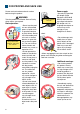
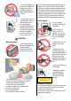
FOR PROPER AND SAFE USE Power supply: Please read and understand each caution before using this product. WARNING Minolta AC Adaptor AC-U10 Take the product to a Minolta Service Facility when repairs are required. Basic operation: Keep inflammable products away from the scanner 35mm 6 • Do not use the product near inflammable gases or liquids such as gasoline, benzine, or paint thinner. Do not use inflammable products such as alcohol, benzine, or paint thinner to clean the product.
• Store this product out of reach of children. Be careful when around children, not to harm them with the product or parts. 35mm • If the product emits a strange odour, heat, or smoke, discontinue use. Immediately unplug the power cord taking care not to burn yourself. The continued use of a damaged product or parts may cause injury or fire. 35mm • The required operating environment must be between 10°C and 35°C with less than 80% humidity.
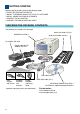
GETTING STARTED Before using this product, please take following steps: • CHECK THE PACKAGE CONTENTS • INSTALL THE DIMAGE SCAN ELITE II UTILITY SOFTWARE • INSTALL ADOBE PHOTOSHOP ELEMENTS • CONNECT THE AC ADAPTOR • CONNECT THE USB OR IEEE1394 CABLE CHECKING THE PACKAGE CONTENTS The following is included in this package: 35mm film holder (FH-U1) DiMAGE Scan Elite II Slide mount holder (SH-U1) AC adaptor (AC-U10) Power cable for AC adaptor AC-U10 35mm USB cable (UC-1) USA, European Canada, continent and
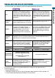
INSTALLING THE UTILITY SOFTWARE CPU Pentium or later processor. Pentium III processor is recommended when scanning with 16 bit output or using Digital ROC or GEM. Operation is not guaranteed for custom or home built computers. Power PC G3 or later (Except 68 K Macintosh and Mac OS compatible units). Power Macintosh G4 or later is recommended when scanning with 16 bit output or using Digital ROC or GEM.. Operating system Preinstalled Windows 98, 98 Second Edition, 2000 Professional, XP or Me.
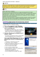
INSTALLING DRIVER SOFTWARE – WINDOWS CAUTION The anti-virus system extensions may conflict with the operation of the software installer. Before installing the scanner utility software, remove or disable any extensions before launching the installer. Replace or re-enable the extensions when the installation is complete. TIPS About TWAIN drivers and plug-ins The scanner can be launched directly from an image-processing application like Adobe Photoshop Elements.
4 Click “Next” to view the license agreement. Click “Yes” to accept the agreement and continue. GETTING STARTED • Read the entire agreement carefully before continuing. If you do not agree to the terms of the license agreement, click “No” to exit the setup program. 5 To install the software in the default folder (C:\Program Files\DS_Elite2), click “Next”. • To install the software in another folder, click “Browse...” to display the folder selection window.
INSTALLING DRIVER SOFTWARE – MACINTOSH 1 Turn on the computer to start the Mac OS. 2 Insert the DiMAGE Scan Elite II CD-ROM into the CD-ROM drive. • Dimage Scan Elite2 CD-ROM icon will appear on the desktop. 3 Double-click on the DiMAGE Scan Elite 2 icon. • The driver, manual, and acrobat reader folders will appear. 4 Double-click on the driver folder. • The language folders will appear. 5 Open the English language folder, then double click on the DS Elite 2 installer.
GETTING STARTED 10 Any software that is running must be stopped before the scanner driver can be installed. Click “Continue” to shut down any active applications and continue the installation routine. • Clicking “Cancel” will end the installation routine. 11 A screen confirming the successful installation of the software will appear. Click “Restart” to exit the installation program and restart the computer. • To exit the installer without restarting the computer, click “Quit”.
INSTALLING ADOBE PHOTOSHOP ELEMENTS Take time to register your copy of Photoshop Elements with Adobe. You can register online, by fax, or by mail. The software can be registered online during installation by following the instructions on the installer screens. To register by fax or mail, read the instructions in the registration folder located in the technical-information folder on the Adobe Photoshop Elements CD-ROM.
GETTING STARTED 6 Read the cautions on the setup screen. If no other applications are running, click “Next”. • Click “Cancel” to exit the setup routine to stop any applications that may be running. To start the installation routine again, double click on the elements icon in My Computer. The routine will start from step 2. 7 Click on the preferred language and click “Next” to continue. 8 The end-user license agreement will appear.
INSTALLING ADOBE PHOTOSHOP ELEMENTS – WINDOWS 11 Fill in all the fields on the user information screen. Click “Next”. • The serial number is found on the back of the CD-ROM case. Enter the serial exactly as it is displayed. 12 Check the registration information on the confirmation screen. If all information is correct, click “Yes”. Tarou X Minolta Co., Ltd. XXXXXXXXXXXXXXXXXXXXXXXX • To correct the information, click “Back” to return to the user information screen.
GETTING STARTED 1 Turn on the computer to start the Mac OS. 2 Insert the Adobe Photoshop Elements CD-ROM into the CD-ROM drive. • The Adobe Photoshop Elements CD-ROM icon will appear on the desktop. 3 Locate the Photoshop Elements installer in the Adobe Photoshop Elements folder located in the appropriate language folder. 4 Double-click on the Install Photoshop® Elements icon. 5 The Adobe Photoshop Elements screen will appear. Click “Continue”. 6 Use the drop-down menu to select the preferred language.
INSTALLING ADOBE PHOTOSHOP ELEMENTS – MACINTOSH 10 Select the installation method from the pop-up menu at the top left of the installer screen. Click “Install” to begin installation. • The easy-install option will install the required software. If only specific programs need to be installed, select the custom-install option; click the check box of the files to be installed. 11 Fill in all the fields on the user information screen Click “Next”. • The serial number is found on the back of the CD-ROM case.
NAMES OF PARTS APS adaptor mark Pull down the front door to this position when inserting the optional APS adaptor. Front door When the scanner is not in use, close the door to prevent dust from entering the unit. 35mm Power switch Indicator lamp This lamp indicates when the scanner is on. The lamp will blink while the scanner is initialising. IEEE 1394 port USB port DC terminal Eject button This button ejects the film holder, and rewinds the film in the APS adaptor.
@ @ +@ +~+{ $ % &' * +<%& & &! & %< &' = > ? @!* & ' < !& Q Z & +[ 35mm ! ! " # ! $ ' ! ' + ! ' ! #
DISCONNECTING THE CABLE WITH WINDOWS GETTING STARTED With Windows 2000, Me, or XP always close the utility software before disconnecting the IEEE 1394 or USB cable while the computer and scanner are on. Before unplugging the IEEE 1394 cable with Windows Me, complete the “Unplug or eject hardware” operation by double-clicking on the of “Unplug or eject hardware” icon on the task bar (see page 87).
EASY SCAN UTILITY Easy Scan Utility is a simple, automatic scanning application. The utility works as a stand-alone program, and cannot be launched through another application. Simply follow the ten steps to create perfect, trouble-free scans: 1. 2. 3. 4. 5. 6. 7. 8. 9. 10.
2. LOADING THE FILM HOLDER Using the included holders, the DiMAGE Scan Elite II can scan mounted or unmounted... • Colour negatives • Colour positives • Black and white negatives • Black and white positives APS (Advanced Photo System) film can also be scanned using the optional APS adaptor AD-10. CAUTION Remove any dust from the film before placing it in the film holder. Only use brushes or compressed air specifically for photographic film.
LOADING THE FILM HOLDER LOADING THE SLIDE MOUNT HOLDER – SH-U1 • The slide mount holder SH-U1 accommodates up to four slides. Slide mounts must be thicker than 1 mm and thinner than 2 mm to be used in the holder. Do not use glass mounted slides. APS slide mounts can be used. 1 Hold the slide mount holder so that the slide slots are to the top and the frame numbers are up-side-down and face up. 2 Insert slides into the slots with the emulsion down.
CAUTION • Do not remove the APS film from the cassette. • When using the APS adaptor, if the scanner makes a strange sound or the “Film advance error” warning appears, eject the APS cassette immediately (see page 29), and do not insert it again. • Minolta is not responsible for any loss or damage caused from the operation of this product. 3. INSERTING THE FILM HOLDER For information on loading the film holder, see page 23.
INSERTING THE FILM HOLDER INSERTING THE APS ADAPTOR AD-10 (SOLD SEPARATELY) 1 Open the front door of scanner until the top of the door lines up with the APS mark – . 35mm 2 With the scanner contacts face up, insert the adaptor into the scanner until it stops. 35mm • The scanner detects the holder and automatically loads the film from the cassette. • To eject the holder, push the eject button. The scanner will automatically rewind the film. Do not remove the adaptor until the rewind motor has stopped.
5. MAKING AN INDEX SCAN An index scan displays a thumbnail image of all the images in the holder. This is especially useful when a selection needs to be made between similar negatives on one strip of film. To make an index scan, click on the radio button next to the setting. Click “Next >” to start the scanner. • When an index scan is not needed, click “No Index Scan”. • If an index scan is made without a film holder or APS adaptor, the “Please set holder properly” message will appear.
8. CHOOSING DIGITAL ICE/ROC/GEM PROCESSING The scanned image can be enhanced with Digital ICE3 image processing. These tools cannot be used with traditional black and white film. Click on the buttons to choose the image processing to be applied to the scanned images. Click “Next >” to continue. • Digital ICE reduces the effect of dust, flaws, scratches, and fingerprints on the film surface. This cannot be used with Kodachrome film. • Digital ROC restores the colour of faded film.
TURNING OFF THE SCANNER 1 Press the eject button to unload the film holder or APS adaptor. • The scanner automatically ejects the 35mm film or slide mount holder to the initial inserting position. Do not touch or hinder the holder while it is moving. • When using the optional APS adaptor, the scanner automatically rewinds the film when the eject button is pressed. Do not remove the adaptor until the rewind motor has stopped. 35mm 2 3 2 Close the front door.
STANDARD SCAN UTILITY The Standard Scan Utility allows individual selection over scan settings to optimise the reproduction of the film image. The following flow diagram shows the usual scanning procedure: 1. LAUNCH THE STANDARD SCAN UTILITY (see page 31) The utility can be launched through an image-processing software or as a stand-alone application. 2. SET UP THE SCANNER (see page 33) Settings to control basic scanner operation can be made. 3. LOAD THE FILM HOLDER (see page 36) 4.
1. LAUNCHING THE STANDARD SCAN UTILITY CAUTION Confirm the cable is securely connected and the front door of the scanner is closed before turning on the scanner and launching the software. If the front door is open before launching the software, the scanner cannot initialise and will not accept the film holder. The Standard Scan Utility can be launched through an image processing application like Adobe Photoshop Elements, which allows the image to be processed in the application after it is scanned.
CAUTION Confirm the cable is securely connected and the front door of the scanner is closed before turning on the scanner and launching the software. If the front door is open before launching the software, the scanner cannot initialise and will not accept the film holder. Do not launch both the TWAIN model and independent utility together. Only one needs to operate at any time.
2. SETTING UP THE SCANNER MAIN WINDOW When the software is launched, the main window will open. For details on the scan-setting dialog box, see page 74. Film-format list box To select 35mm or APS film(see page 36). Film-type list box Colour negative, colour positive, B&W negative, and B&W positive (see page 36). Preferences button To set scan preferences (see page 34). Custom Wizard button To make automated scan settings (see page 83).
SETTING SCANNER PREFERENCES 1 Click the preferences button to open the preferences dialog box. 2 Select the preferences as desired. Auto-expose-for-slides check box Checking this option activates the auto-exposure function during the prescan and final scan of colour slides. Since the density range of colour slides is relatively uniform, adjusting the exposure for each slide is unnecessary.
Multi-sample list box Multi-sampling can be used when making scans. This function reduces random noise in the image by analysing the data of each sample scan. The more samples taken, the less random noise in the image and the longer the scanning time. Select from one of five settings: • • • • • OFF 2X 4X 8X 16 X No sampling. Makes two samples. Makes four samples. Makes eight samples. Makes sixteen samples.
3. LOADING THE FILM HOLDER Load the film holder or APS adaptor, and insert it in the scanner. See page 23 for details on how to place film or slides in the film holder. 35mm 35mm 35mm 2 2 3 35mm film holder FH-U1 Slide mount holder SH-U1 APS adaptor AD-10 (Optional) 4. SETTING THE FILM FORMAT AND TYPE 1 Select the film format from the drop-down list. • 35mm or APS film formats can be selected. The default setting is “35mm.” 2 Select the film type from the drop-down list.
5. INDEX SCAN The index scan is a low-resolution scan used to show thumbnail images of all the frames in the film holder. Index scans are particularly useful when selecting images from negatives. If an index scan is not needed, simply click on the thumbnail frame of the corresponding frame in the film holder to scan a specific image. The time required for an index scan depends on the performance of your computer. Two index-scan options are available: speed or quality.
MAKING AN INDEX SCAN Click on the index-scan button the main window. in • All the frames in the film holder will be scanned. • To cancel the index scan, click the cancel button in the small dialog box that appears during the scan, or... :press the escape key :press the command ( scan message appears. ) key and period (.) at the same time until the cancelling-index- • Images can be prescanned or scanned without making an index scan (see pages 43 and 81).
ROTATING OR FLIPPING THE INDEX FRAMES Click the appropriate button to rotate or flip the prescan image. Rotate 90˚ counterclockwise. Rotate 90˚ clockwise. STANDARD SCAN UTILITY Flip horizontally. Flip vertically. Flipping the image vertically creates a mirror image and does not simply rotate it 180°.
FIT-TO-WINDOW BUTTON This function automatically sizes the index images to fit the utility window. Click the fit-to-window button . • When the fit-to-window button is clicked again, the index images are displayed at their original size. REVERSING THE FRAME ORDER Some cameras reverse-wind the film so the last frame is exposed at the beginning of the roll. When scanning film strips, the order of the index thumbnails can be reversed to correct the chronology. Click the reverse-frame-order button .
SAVING AN INDEX FILE The index thumbnails can be saved as an index file. The index file can be loaded into the scanner so that the index scan does not need to be made again. All the frames in the film holder, including empty frames, must be scanned before the index thumbnails can be saved. 1 Click the save index-file button . 2 Enter the file name and select the file destination. Click “Save”. • The displayed index images can be saved regardless if the film holder is in the scanner or not.
6. MAKING A PRESCAN Prescanning allows cropping and image processing to be applied to the image before the final scan. This allows the image data to be optimised at the time of scanning. PRESCAN TAB Click the prescan tab in the main window to view the prescan window. Rotate-left button To rotate the image 90˚counterclockwise (see page 46). Rotate-right button To rotate the image 90˚ clockwise (see page 46). Flip-horizontal button To flip the image horizontally (see page 46).
MAKING A PRESCAN 1 Select the index frame(s) to be prescanned. 2 Click the prescan button in the main window. • The prescan window will be displayed automatically. • Double clicking on the index frame will activate the prescan even if no thumbnail is displayed in the frame. • Clicking the prescan button when more than one frame is selected will make a prescan of all the selected frames. CROPPING THE IMAGE Cropping is a method of recomposing the image by eliminating unnecessary space around the subject.
CROPPING THE IMAGE MANUAL CROPPING After clicking the auto-cropping button, the cropping frame can be adjusted with the mouse. (A) To enlarge or reduce the cropping frame... Using the mouse, place the pointer over the corners or sides of the cropping frame; the pointer will change to a double arrow (figure A). Simply click and drag the edge of the frame to adjust the cropping. (B) To move the cropping frame...
PRESCANNING THE CROPPED IMAGE Click the crop-prescan button cropped area will be displayed. to prescan the cropped area. Only the • To return to the full prescan image, press the prescan button. FIT-TO-WINDOW BUTTON to automatically fit the prescanned • The prescanned image is automatically magnified or reduced to fit the utility window. To resize the utility window, see page 38. • To return the prescan to its original size, click the fit-to-window button again.
ROTATING OR FLIPPING THE IMAGE Click the appropriate button to rotate or flip the prescan image. Rotate the image 90˚ counterclockwise. Rotate the image 90˚ clockwise. Flip the image horizontally. Flip the image vertically. Flipping the image vertically creates a mirror image and does not simply rotate it 180°.
ZOOMING The prescan image can be enlarged or reduced to examine areas within the image. 1 Click the zoom button . • The mouse pointer changes to the plus magnifying glass. • When the fit-to-window function is active, the zoom button cannot be used. 2 Click on the area in the image to be enlarged. • The clicked position becomes the centre for zooming. • The plus sign disappears from the magnifying glass icon when the image is at its greatest magnification.
AUTO EXPOSURE AE area selection is an advanced function to control the scan exposure. This function allows the selection of a small area within the image to be used to determine the scan exposure. The AE lock function sets the scanner exposure based on the exposure of a specific prescan. This exposure can be applied to scans of different images. These two functions are especially useful with negative film. AE area selection and AE lock can be used with negatives and slides.
AE LOCK The exposure obtained with AE area selection or a prescan can be applied to other images. This function is useful when scanning a series of high and low-key images that have consistent exposures. Also, when scanning a bracket series on negative film, by locking the exposure on one frame, the prescans of the other frames will show the exposure difference in the bracketed series.
MANUAL FOCUS The scanner can be focused manually using the focus meter. 1 Click the manual-focus button . • The mouse pointer will change to the manualfocus icon. • To cancel the function, click the manual-focus button again. 2 Click on the area of the image to be used for focus. • The focus meter window will appear. 3 Adjust the slider using the mouse until the black and white bars are at their longest extension for sharpest focus. • The black bar indicates the change in focus.
CROPPING APS IMAGES When APS film format is selected, the CHP button is displayed in the prescan window. Clicking the CHP button cycles the cropping frame through the “C,” “H,” and “P” APS framing formats. When using the image-correction tools, only the cropped area is displayed. H Click the CHP button until the desired frame is displayed. • The cropping area can be adjusted or moved using the mouse. To move the frame, place the mouse pointer within the framed area and then click and drag.
7. IMAGE CORRECTION To optimise the scan data, the image can be processed before it is scanned IMAGE CORRECTION TAB Click the correction tab in the main window to view the correction window. Tone-curve/Histogram button Graphic control over colour, contrast, and value (see page 53). Brightness/Contrast/Colour-balance button Slider control over colour, contrast, and values (see page 62).
TONE CURVES AND HISTOGRAM Click the tone curve/histogram button to open the dialog box.
TIPS RGB and CMYK The RGB colour model is an additive process that uses the primary colours of light: red, green, and blue. An additive colour system mixes the three colours to recreate the entire spectrum of light. If all three colours are mixed, white light is produced. Television sets and computer monitors use RGB to create images. The CMYK colour model is a subtractive process that uses the secondary colours: cyan, magenta, and yellow.
CHANGING THE TONE CURVES 1 Place the mouse pointer over the tone curve. Click and drag the curve. • Each time the tone curve is clicked, a new node will be attached to the curve. The nodes can be moved by clicking and dragging. • The input and output levels of the node are displayed as it is moved. The input level (horizontal axis) refers to the original scan, and the output level (vertical axis) refers to the correction applied to the image.
A QUICK GUIDE TO TONE CURVE CORRECTIONS Image processing is a highly specialised and difficult field that takes years of practice to master. This basic guide to using tone curves covers a few simple procedures to improve your pictures. For more about digital-image processing, consult your local book dealer about self-help guides on this subject. ABOUT THE TONE CURVE The bottom left portion of the graph represents the dark colours and shadow areas of the image.
INCREASING THE CONTRAST OF AN IMAGE The contrast of an image can be changed. The light blue 45° line on the tone curve chart represents the original contrast of the scanned image. Making the angle of the tone curve greater than 45° will increase the contrast of the image. Making the angle less than 45° will reduce the contrast. With the RGB channel selected, click on the tone curve near the top and bottom to add two nodes. Slightly move the top node up and the bottom node down.
WHITE, BLACK, AND GRAY POINT CORRECTIONS Advanced image corrections can be made by specifying a white, black, and gray point within the image. Locating an appropriate neutral area within the image is critical to correctly calibrate the software. When the dropper tool is selected, the RGB display is active and can be used to evaluate the image area. 1 Click the white-point button . • The mouse pointer changes to the white dropper tool.
6 Click a neutral area of the image to be defined as the gray point. • The area used to calibrate the gray point must be neutral. The brightness level of the area is not important, but if the area has a definite colour, the image will not be colour balanced correctly. 7 Press the apply button to show the change on the histogram. • Click the reset button to cancel all corrections. SETTING THE WHITE AND BLACK POINT VALUES The white and black-point values are set to 255 and 0 for each RGB level.
HISTOGRAM CORRECTIONS The histogram indicates the distribution of pixels with specific brightness and colour values inside the cropping frame. Using the histogram can maximise the output of the image data. Changes made with the histogram are also displayed on the tone curve. AUTO SETTING Click the auto-setting button. • The auto-setting function automatically adjusts the tone curve and histogram to maximise image data.
COLOUR CORRECTIONS WITH THE HISTOGRAM 1 Click the colour-histogram button to view the red, green, and blue histograms. • The tone curve and histogram dialog box extends to the right to show the R, G, B channel histograms. • Click the histogram RGB display button again to close the RGB histograms. 2 Use the slider or enter values in the text boxes to adjust the histograms. STANDARD SCAN UTILITY • The changes are reflected in the prescan image. • Click the reset button to cancel any changes.
BRIGHTNESS/CONTRAST/COLOUR CORRECTIONS This palette allows easy corrections to be made to brightness, contrast, and colour. 1 Click on the brightness/contrast/colour-balance button correction palette. 2 Drag the brightness, contrast, or colour sliders, or enter specific values in the corresponding text box to make corrections. to open the • Dragging each slider to the right or inputting a positive number in the text box increases the brightness, contrast, and colour.
HUE/SATURATION/LIGHTNESS CORRECTIONS This palette adjusts the image in reference to the HSB colour model. These controls can be used to manipulate the colour image rather than producing a realistic representation. The HSB colour model defines colour based upon human perception rather than photographic processes. Hue refers to each separate colour in the model. Saturation is how vivid each colours is. Lightness describes how bright or dark a colour is in the colour space.
VARIATION CORRECTIONS The variation dialog box allows an image to be corrected by comparing it to other slightly corrected images surrounding it. This is an easy method to correct images for individuals who are inexperienced in image processing or photofinishing. 1 Click the variation button . • The variation dialog box appears. 2 Click the arrow next to the variation list box to select the image quality to be corrected: colour balance, brightness and contrast, or saturation.
BRIGHTNESS & CONTRAST VARIATION Eight images with a slight correction to brightness and contrast are displayed around a thumbnail of the uncorrected prescan image. 1 Drag the variation-step slider, or enter the correction step into the variation-step text box to set the degree of correction. • The initial setting is 10. The step can be set between 1 and 20.
SELECTIVE-COLOUR CORRECTIONS Selective-colour correction is an advanced technique to refine the colours in the image. The colour of each process colour, cyan, magenta, yellow, and black, can be used to adjust the six separate colour groups in the image: red, green, blue, cyan, magenta, and yellow. This type of correction is effective in changing a specific colour without influencing any of the other colours in the image.
• Shadow protection level: can be adjusted between 0 and 255. The default setting is 16. To limit the sharp subject pixels in the shadows. When the luminance level is greater than the shadow protection level, that pixel is recognised as a sharp pixel. CANCELLING IMAGE CORRECTIONS UNDOING AN IMAGE CORRECTION When the undo button celled. is clicked, the last image correction is can- Undo button REDOING A CANCELLED IMAGE CORRECTION When the redo button reapplied.
SAVING AND LOADING IMAGE CORRECTIONS All corrections applied to an image can be saved as a correction Job. The correction Job can be loaded into the utility at any time, and the correction settings can be applied to different images. SAVING AN IMAGE-CORRECTION JOB 1 Click the save image-correction-Job button to save the current image-correction settings. • The registration dialog box appears. 2 Input the Job name and click “OK”. • The current image-correction settings are saved as an image-correction Job.
DIGITAL ICE, ROC, AND GEM CORRECTIONS DIGITAL ICE3 SYSTEM REQUIREMENTS Digital ICE3 is an collection of powerful image-processing tools: ICE, ROC, and GEM.
DIGITAL ICE Digital ICE (Image Correction Enhancement) eliminates surface defects (dust, scratches, fingerprints, mould, etc.) from the film image during scanning. Click the Digital-ICE button button to view the results. to activate the function. Press the prescan • Digital ICE processing is applied to the prescan and final scan. • Digital ICE cannot be used with Kodak Kodachrome film. • Digital ICE cannot be used with traditional black and white films.
DIGITAL ROC The Digital ROC (Reconstruction of Colour) can restore the faded colour of old film. Click the Digital-ROC button can button to view the results. to activate the function. Press the pres- • When Digital ROC is used, the prescan also makes the final scan. When the final scan is made, the image data is simply processed and saved. While the final scan is relatively fast, the prescans require more time.
DIGITAL GEM Digital GEM (Grain Equalisation and Management) reduces the effect of grain in colour film. Grain is a sandy texture that can sometimes be seen smooth uniform areas of the image, such as the sky. Grain is more pronounced in fast film. Digital GEM cannot be used with traditional black and white films.
6 Adjust or move the Digital-GEM sample area to select the image area to be used to evaluate the Digital-GEM correction. • Choose a smooth uniform area to evaluate. Skin is a good subject. • Using the mouse, place the pointer over the corners or sides of the GEM sample area frame; the pointer will change to a double arrow. Simply click and drag the edge of the frame to adjust the area. By placing the pointer in the centre of the frame, the pointer will changed to a four-pointed arrow.
8. SCAN SETTINGS SCAN SETTING DIALOG BOX Before making the final scan, the input and output parameters must be specified. While it is possible to input the scan settings yourself, DiMAGE Scan Elite II gives you an easier choice – the Job function, which automatically loads the scan settings based on the final use of the image. Click the prescan or index scan tab to view the scan-setting window. • The scan-setting dialog box is located on the left of the tab.
USING JOB FILES The Standard Scan Utility contains approximately 110 preinstalled Job files to cover a wide range of image use. 1 Click the load Job button . • The Job-selection dialog box will appear. 2 Select a category from the drop-down list. 3 Click a Job file name to select it. Click “OK” to apply the Job to the image. STANDARD SCAN UTILITY • The scan settings of the selected Job file are displayed on the right side of the selection window.
USING JOB FILES JOB CATEGORIES Custom User-created scan settings (see page 74). Colour Laser Printer For digital colour copiers and colour laser printers. Uses an output resolution of 600 dpi with four paper sizes from A4 Quarter through Letter Eighth. Photosensitive For printers that use photosensitive/photographic material. Uses an output resolution of 400 dpi with five paper-sizes from A5 full through Postcard 4x6. Ink Jet & Dye-Sub Printer For Ink Jet and Dye-sublimation printers.
INPUTTING SCAN SETTINGS MANUALLY Input-resolution list box Values can be selected from the drop-down list or be entered into the box directly. The resolutions on the list are 2820, 1410, 940, 705, 470, 352, and 282 dpi. The default setting is 705 dpi. Output-resolution list box Values can be selected from the drop-down list or be entered into the box directly. The resolutions on the list are 2400, 1440, 1200, 800, 720, 600, 400, 360, 350, 300, 240, 200, 180, 150, 96, 72, and 36 dpi.
INPUTTING THE SCAN SETTING BY YOURSELF TIPS Resolution and output size The resolution can be expressed in dpi (dots per inch). This refers to how many pixels are placed along one linear inch. The resolution of 350 dpi, which is commonly used in the commercial printing field, means that an area of one square inch would use 122,500 pixels. The larger the resolution, the greater the detail in the image. However, as the resolution increases, so does the file size.
EXAMPLE: SETTING OUTPUT BY PRINT SIZE AND OUTPUT RESOLUTION 1 Select millimetres from the unit list box. 2 Enter the output resolution in the output-resolution list box. In this example, enter 300. • This example is based on a printer with a 300 dpi output. 3 Enter the output size: in this example, enter 148 for the width and 100 for the height. Click on the output-size lock button to fix the values. 4 Use the mouse to adjust the cropping frame over the prescan image to define the final scanning area.
SAVING A JOB FILE Frequently used scan settings can be saved. 1 With the scan settings to be saved in the scan settings window, click on the save Job button . • The Job-registry dialog box appears. 2 Select the category in which to save the settings from the drop-down menu. 3 Enter the Job file name. Click “OK” to save the settings. • The Job file name can contain up to 24 characters. DELETING A JOB FILE A Job file can be deleted. 1 Click the Job load button.
9. MAKING THE FINAL SCAN WHEN USING THE UTILITY THROUGH AN IMAGE-PROCESSING APPLICATION 1 Click the scan button dow. in the main win- • The final scan will start. • When the scanning is complete, the image is automatically loaded into Photoshop Elements. 2 Close the utility software. • If the close-utility-after-scanning option is active in the preference box, the utility will automatically shut down. 3 Save the image with the Photoshop Elements file menu.
FINAL SCAN AND SAVING TIPS File types BMP – the bitmap image file type is used in Windows. This file type can be opened in the print software installed in the Windows operating system. JPEG – the image file can be compressed to reduce the file size. The compression ratio can be selected when saving. The higher the compression ratio, the smaller the file size, and the more deterioration in the image quality. TIFF – this high-resolution bitmap can be opened on any computer platform.
CUSTOM WIZARD This function automates the scanning procedure. 1 Set the film holder in the scanner. 2 Click the Custom Wizard button . 3 On the Custom-Wizard-setting dialog box, select “New” from the Custom Wizard settings. Click “Next”. • The film format and type should be entered. See details on page 36. • The frame(s) to be selected can be checked by checking the radio box. 4 On the film dialog box, select the film format, film type, and frame number(s) of the images to be scanned. Click “Next”.
CUSTOM WIZARD 7 Enter scan setting. Click “Next”. • See page 74 for details on scan settings. • When the window opens, the last scan settings made will be displayed. • When auto-cropping function is active, blank space around the image area will be automatically eliminated. Inside-edge cropping crops the image just inside the image area. Outside-edge cropping crops the image to the outside limit of the image area. Inside-edge cropping is recommended for mounted slides.
QUITTING THE STANDARD SCAN UTILITY To turn off the scanner at the end of a scanning session, following steps 1 through 4. To restart the computer, following steps 1 through 3. 1 Quit the Standard Scan Utility software or close Photoshop Elements. 2 Press the eject button to unload the film holder or APS adaptor. • The scanner automatically ejects the 35mm film or slide mount holder to the initial inserting position. Do not touch or hinder the holder while it is moving.
APPENDIX IEEE 1394 AND USB INTERFACES IEEE 1394 AND USB The IEEE 1394 or FireWire interface and the USB interface allow data to be transferred between a computer and devices like scanners, printers, and digital cameras. The advantages to these interfaces are: • Faster data transfer rates (100Mbps or more with IEEE 1394, 12Mbps with USB1.
WHEN USING THE IEEE 1394 CABLE WITH WINDOWS ME 1 Quit the utility software. 2 Confirm the DiMAGE Scan Elite II indicator lamp is on and not blinking. • If other USB or IEEE devices are connected to the computer, confirm that they are not in operation before continuing. 3 Double-click on the “Unplug or Eject Hardware” icon on the task bar. • The unplug-or-eject-hardware dialog box will appear. 4 Select “Minolta DiMAGE Scan Elite 2” and click “Stop”. • A confirmation screen will appear.
COLOUR MATCHING Each output device (monitor or printer) defines colour and contrast differently. To ensure the reproduction of the image on the monitor matches the reproduction of the image from the printer, the colour space for both devices must be defined. Colour matching is activated in the preferences box (see page 34). Colour matching increases the scanning time. The DiMAGE Scan Elite II colour matching function matches the scanned colour with specified colour spaces.
OUTPUT COLOUR SPACE The choice of output colour space is dependent on how the image will be reproduced. For most home use where the image is displayed on a monitor or printed with a small printer, sRGB colour space is adequate. Other colour spaces have been included for professional and technical applications. For recommendations for colour space use, see page 90. sRGB The colour space promoted by Hewlett Packard and Microsoft.
SETTING THE MONITOR ICC PROFILE 1 Click the use-ICC-profile check box. 2 Click the load ICC-profile button. • The operating systems file-open dialog box will appear. 3 Open the ICC profile for the monitor in use. • The ICC profiles can be found at the following locations: 98/98SE/Me : Select “Windows” folder -> “System” folder -> “Colour” folder.
SCANNER NOTES Scanner colour profiles When installing the utility software, the scanner profiles listed below will be automatically installed in the colour folder in Windows, and in the ColorSync profile folder in Macintosh. These profiles have been included for advanced colour matching with profile to profile conversions in sophisticated image-processing or DTP applications. When using these profiles, the colour reproduced may not be the same as the colour matching system in the utility software.
INSTALLED FILES AND FOLDERS When installing the utility software, the following files and folders are installed. C: Program Files DS_Elite2 Windows Twain.dll Twain32.dll Twunk_16.exe Twunk_32.exe DS Elite2 System folder Exporter folder Help folder Job folder*1 Profile folder Prefs folder DS_Elite2.exe DS_Elite2Easy.exe Readme.txt System MFSLib2888.dll MFSBaseLib2888.dll DICEMLT002.dll DRAGMLT002.dll MCMLDS.dll Colour MLTF2920.icc*2 MLTF2920p.icc*2 twain_32 DS_Elite2 DS_Elite2.
JOB FILE LIST • • To save new Job files, see page 80. Do not handle the Job file using Explorer in Windows or the Finder in Macintosh. 35MM FILM Category Job Name Default ColorLaserPrinter Output Res. Mag. Unit Input Size W H Input Lock Output Size W H Output Lock 705 300 235 pixel 1008 672 OFF 1008 672 OFF A4Quarter A4Eighth LetterQuarter LetterEighth 2602 1846 2676 1990 600 600 600 600 433 307 446 331 mm mm inch inch 34.18 34.2 1.22 1.22 24.25 24.27 0.95 0.
JOB FILE LIST APS FILM Category Job Name Default Default ColorLaserPrinter Input Res. Output Res. Mag. Unit Input Size W H Input Lock Output Size W H Output Lock 705 300 235 pixel 832 480 OFF 832 480 OFF A4Eighth LetterEighth 2584 2785 600 600 430 464 mm inch 24.42 0.87 17.33 0.68 OFF OFF 105 4.05 74.5 3.16 ON ON Photosensitive A5Full LetterQuarter 2L PostCard4x6 2820 2497 2820 2350 400 400 400 400 705 624 705 587 mm inch mm inch 29.79 0.87 25.25 1.02 17.3 0.68 17.
TECHNICAL SPECIFICATIONS Scan type: Film type: Film formats: Scanning dimensions: Optical input resolution: Image sensor: A/D conversion: Output data: Dynamic range: Light source: Focusing: Other: Interface: Power supply: Power consumption: Dimensions (W x H x D): Weight (approx.): Scan times (approx.): Moving film, fixed sensor, single-pass scan Negative and positive, colour and monochrome Mounted and unmounted 35mm film. Mounted APS film. APS cassette with optional adaptor. 35mm – 24.21 x 36.
TROUBLESHOOTING This section covers minor problems with scanner operation. For major problems or damage, or if a problem continues to reoccur frequently, contact your dealer or a Minolta Service Facility. SYMPTOM or MESSAGE SOLUTION When starting up the utility software, Error=4 – could-not-confirm-scanner- connection message appears. Confirm the cable is securely connected between the computer and scanner. Turn the scanner off and on. Click “OK” to continue.
USER TECHNICAL SUPPORT Please contact your dealer for information regarding installation, IEEE 1394 interface recommendations, or application compatibility. If your dealer is unable to help you, contact an authorised Minolta Service Facility.
INDEX 16 bit.....................................................................................34 16 bit linear...........................................................................34 35mm film holder..............................................................8, 23 35mm film-holder mark ..................................................19, 25 8 bit.......................................................................................34 A AC adaptor AC-U10 ...........................................
L M N O P Q Quitting the Standard Scan Utility ........................................85 R Redo button....................................................................52, 67 Redo a cancelled correction.................................................67 Reset button (Tone-curve/Histogram tab) ............................53 Reset button (Scan settings) ................................................74 Resolution and output size ...................................................