® 1800668-001C EDNord - Istedgade 37A - 9000 Aalborg - telefon 96333500 English magicolor 2210 Installation Guide
Thank You Thank you for purchasing a magicolor 2210. Your magicolor 2210 is specially designed for optimal performance in Windows, Macintosh, and networking environments. English Trademarks The following are registered trademarks of MINOLTA-QMS, Inc.: QMS, the MINOLTAQMS logo, Crown, CrownNet, and magicolor. Minolta is a trademark of Minolta Co., Ltd. Other product names mentioned in this guide may also be trademarks or registered trademarks of their respective owners.
English Contents Getting Acquainted with Your Printer ........................................................... 1 Features 1 Front/Right Side View 1 Front Internal View 2 Left/Rear Side View 2 Location Requirements 2 Documentation Set ......................................................................................... 3 Setting up Your Printer ...................................................................................
English Administration Menu 21 Selecting a Message Window Language .....................................................22 Printer Control Panel 22 About the Interface Panel .............................................................................23 Software Utilities CD-ROM ............................................................................24 Regional Settings 24 Drivers and Utilities 24 Installing Printer Drivers and Software .......................................................
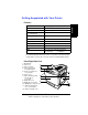
Getting Acquainted with Your Printer Print Speed 5/20* pages per minute SDRAM 128 MB Resolution 1200 x 1200 dpi 500-sheet Letter/A4/Legal (Upper Media Tray) z Multipurpose Tray z Internal IDE Hard Disk • Time-of-Day Clock • Lower Feeder Unit • 5-bin Mailbox • Duplex Unit • Notes *5 = color; 20 = monochrome black.
Front Internal View English 1—Toner ejection lever 2—Toner cartridge slot 3—Toner carousel release button 4—Toner rotation knob 5—Waste toner pack 6—Transfer belt unit right release lever 7—OPC drum cartridge g c h i d e f Left/Rear Side View 1—Ventilation grille 2—Interface panel 3—AC power connector 4—Top cover 5—Output tray 6—Main power switch 7—Hand grips for moving printer 8—Media tray (left side) f g c h i d e j Location Requirements Front 20 inches (50 cm) 8 inches (20 cm) 28 inches
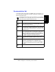
Documentation Set Look for the movie camera icons in the manuals. If you’re using the Acrobat PDF version of this guide, click the icon to play a QuickTime video clip of the procedure described in the text. Quick Setup Guide Use this sheet when unpacking the printer. Service & Support Guide This lists global sources of service and support for your printer. Further information about MINOLTA-QMS printers is available through the Internet. Installation Guide You’re looking at this document right now.
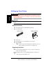
Setting up Your Printer WARNING! English The printer weighs 87.1 lbs (39.5 kg) without consumables. To avoid personal injury or damage to your printer, at least two people must lift and move the printer. Attention During installation, do not plug in the printer’s power cord until told to do so.
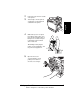
2 Take the tape off of the pull-out carrying bars c and slide them outward from the printer. English 3 Remove the tape from the outside of the printer. 4 With another person’s help, lift the printer from the carton, and place it in its intended location. A third person’s assistance may be required if the printer is lifted above waist level. When lifting and carrying the printer, use the hand grips c and the pull-out carrying bars d. c d 5 Open the front cover.
6 Remove the cardboard/ foam spacers c and the tape d from the laser lens cover. English 5" c The transfer belt left release lever will move to the 4 o’clock position when you remove the spacers. d 7 Pressing on the transfer belt unit front handle with one hand, take the yellow tag attached to the transfer belt unit fixture with your other hand, and pull the fixture straight toward you. This fixture protects the transfer belt during initial transportation.
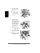
Installing the Waste Toner Pack The waste toner pack collects the excess toner remaining on the OPC drum. Remove the waste toner pack from its plastic shipping bag. Make sure the transfer belt unit left release lever is still set to its correct (2 o’clock) position. 5" 3 If the transfer belt unit left release lever is at its top (12 o’clock) position or the laser lens cover is not firmly seated, the waste toner pack cannot be installed.
Installing the Fuser Oil Roller 1 Push the top cover latch c to open the top of the printer d. d English c 2 3 4 Rotate the two small levers to the unlocked position. Remove the tape from the media exit area. Remove the fuser oil roller from its box. Attention Lift and hold the fuser oil roller only by the handle. Do not allow the roller surface to contact the table or get dirty. This could lower image quality.
Insert the fuser oil roller guides into the guide rails, then carefully lower the roller.I English 5 5" 6 If the guides don’t go down into the guide rails, the top cover cannot be closed. Rotate the two fuser oil roller levers to the locked position. 5" If the fuser oil roller release levers are not correctly set, the top cover cannot be closed.
Close the top cover gently to avoid jarring the fuser oil roller. English 7 Removing the Tape from the Transfer Roller 1 Press the right cover release button c and open the right cover d. c d 2 10 Remove the tape from the transfer roller unit.
Make sure the transfer roller unit handles remain in their down position. English 3 4 Close the right cover. Loading Media Loading the Media Tray 1 2 3 4 Slide out the media tray. Remove the tape and the packing material from the media pressure plate. Push the media pressure plate down to lock it in position. Adjust the media guides to fit the size paper you’re loading.
English Squeeze the retainers, move the guides to the appropriate location (media sizes are listed on the tray), and release the retainers. Attention The media should fit easily between the guides. Improperly adjusted guides may cause poor print quality, media jams, or printer damage. 5 Load the media face-up, short edge toward the right of the tray. Often, an arrow on the media package label indicates the printing-side of the media. A fill limit mark is provided on the inside of the tray.
English Make sure that the paper fits easily between the guides and the paper corners are under the left and right media-separating tabs and are not bent. For further information about loading and using media, refer to chapter 2, “Using Media,” in the User’s Guide. 6 Slide the media tray all the way in. If you have removed the tray from the printer, slightly tilt up the front of the tray to insert it into the guide rails to slide it back in. Loading the Multipurpose Tray 1 Open the multipurpose tray.
Open the media support. 3 Load the media face down, short edge toward the printer. FA C DO E WN English 2 Often, an arrow on the media package label indicates the face-up side of the media. A fill limit mark is provided on the inside of the media guides on the multipurpose tray. The multipurpose tray holds 150 sheets of 20 lb bond (75 g/m²) paper. Attention Load only one type or size of media per tray at a time.
Adjust the media guides to fit the size media you’re loading. LTR LG . EXE. L. English 4 A5 B5 A4 Attention Always adjust the media guides after inserting the media. A guide that is not properly adjusted can cause poor print quality, media jams, or printer damage. 5 Specify the media size in the multipurpose tray by using the MP Size key on the control panel. For further information about loading and using media, refer to chapter 2, “Using Media,” in the User’s Guide.
Plugging in/Turning on the Printer 1 Make sure the printer is turned off. English 2 Plug the printer power cord into the printer and into the dedicated, grounded, surge-protected electrical outlet. WARNING! Do not overload the outlet. For products installed outside North America, do not connect the groundwire to gas or water pipes or grounding for telephones. 3 Turn on the printer. 5" In compliance with UL guidelines, “The appliance inlet is considered to be the main disconnect device.
About the Control Panel „ Three indicators (LEDs) to provide printer status information. „ A message window to display status and configuration information. „ Seven keys to allow you to control the printer configuration through access to frequently used printer functions. English The control panel, located on the front of the printer, allows you to direct the printer’s operation. In addition, it displays the current status of the printer, including any condition that needs your attention.
Key Function English Accesses the printer menu. When you’re changing the printer configuration, press this key to cancel a change (before pressing the Select keys), to return to the previous selection or option for the current menu, and to return to the previous choice when changing character information. The Select key accesses a menu or chooses a displayed menu option, advancing to the next selection or option for the current menu and advancing to the next choice when changing character information.
Printer Menu Overview Menu Chart Conventions „ Some menu choices are marked as optional, indicating that the selection appears in the menu only when the option is installed. „ Defaults are bolded. English The following conventions are used in the menu charts: For information about setting and changing passwords, refer to the CrownBooks.
Operator Control Menu IDLE English Configuration Operator Control Copies Security 001-999 Duplex Off, Long Edge, Short Edge Outputbin Upper, Mailbin1*...
Administration Menu IDLE Administration Communications Emulations Special Pages Startup Options Memory Engine Consumables Miscellaneous Disk Operations*** Security Timeouts Parallel ESP Default TIFF*** CALS*** English Configuration Operator Control Resident NIC Optional NIC* PostScript PCL 5e HP-GL Lineprinter CGM*** LN03+* Trailer Page Print Status CMM Profile Page Registration Pg Header Inputbin Test Page 1 Trailer Inputbin Test Page 2 Status Page Type Header Page Do Start Page Do Sys S
Administration/Communications/Resident NIC/ CrownNet Menu English IDLE Configuration Administration Communications Optional NIC CrownNet Common Mode Emulation EtherTalk Resident NIC Min K Spool LAN Manager Def Job Prio PS Protocol NetWare TCP/IP Selecting a Message Window Language Printer Control Panel The control panel message window provides status and configuration information.
Press Key (Until) Display Reads Online IDLE (and online LED is off) Menu OPERATOR CONTROL Next ( ADMINISTRATION ) Select ADMINISTRATION–COMMUNICATIONS Previous ( ) Select ) Select MISCELLANEOUS—KEYPAD LANGUAGE KEYPAD LANGUAGE—*ENGLISH Next ( )/ Previous ( 5" ADMINISTRATION—MISCELLANEOUS MISCELLANEOUS—SAVE DEFAULTS Previous ( Select English If you want to change the message window language, use the following control panel sequence (slightly dependent upon the model and installed optio
Software Utilities CD-ROM Regional Settings English The Software Utilities CD-ROM checks your computer’s Regional Settings and automatically starts up in the language that you selected if it is supported. In a Windows environment, you may change the opening language by changing the computer’s Regional Settings (double-click on the My Computer icon, then on Control Panel, then on Regional Settings). 5" Other applications on your PC may also be affected by changing the Regional Settings.
Use/Benefit This driver gives you access to all of the printer features, including finishing, color management, and advanced layout on the Windows 2000/NT4 platform. It is designed to be feature-rich while versatile and easy to use. PostScript Printer These PPD files allow you to install the printer for a Description variety of platforms, drivers, and applications.
Installing Printer Drivers and Software English You can install printer drivers and utilities via a parallel or an Ethernet connection. Installing Windows Drivers and Utilities via a Parallel Connection Plug and Play Installation 5" 1 5" 2 26 Ethernet connections don’t support Plug and Play technology. If you’re using an Ethernet network connection, skip to “Installing Windows Drivers and Utilities via an Ethernet TCP/IP Interface Configuration” on page 28.
3 Follow the instructions on the screen to complete the installation of the printer driver. When the installation is complete, the Windows desktop appears. Remove the CD-ROM from the PC, and store it in a safe place. During software installation, you can view online help by choosing the Help button.
Installing Windows Drivers and Utilities via an Ethernet TCP/IP Interface Configuration English Detailed instructions for configuring TCP/IP can be found in the CrownBook (in PDF format on the Software Utilities CD-ROM). DHCP Installation If you use DHCP to install TCP/IP, you must enable DHCP/WINS in Administration/Communications/Resident NIC/CrownNet/TCPIP printer configuration menu. See your network administrator and your CrownBook for further information.
Click on the printer driver for your specific driver and port monitor. Follow the instructions on the screen. English 5 Selecting the Crown Port The Crown Print Monitor for Windows 2000/NT4/Me/98/95 transports print jobs to a print device using the TCP/IP protocol and provides status information to the host. If you installed the Crown Print Monitor, follow the instructions in this section to assign the new Crown port that was created. 1 2 3 4 5 6 From the Start menu, choose Settings.
Crown port that was added during the Crown Print Monitor installation. 7 8 English 5" Choose OK to close the Printer Properties window. Close the Printers window. For additional information about the Crown Print Monitor, see the Crown Print Monitor Administrator’s Guide (in PDF format on the Software Utilities CD-ROM). For information about the print monitor that comes with Microsoft Windows 2000, see your Windows documentation.
PPDs and Utilities (OS9 and Below) Installation 1 Insert the autoloading Software Utilities CD-ROM into your CD-ROM drive. 2 3 4 English This screen should appear. If not, open the Readme file in the Explore button for information on the latest available drivers, PPDs, and utilities. Double-click the INSTALL icon. Follow the instructions on the screen. PPDs and Utilities (OSX) Installation For installation of PPDs and utilities for OSX, refer to the MINOLTA-QMS website at www.minolta-qms.
English Troubleshooting Although the magicolor 2210 GN is designed to be highly reliable, you may occasionally experience a problem. The following helps you to identify the cause of the possible installation problems and suggests some solutions related to installation. For detailed troubleshooting information, refer to “Troubleshooting” in the User’s Guide. Solving Problems during Installation Symptom Cause Solution No lights or messages appear on the control panel.
Solution The printer is connected to an outlet with a voltage or frequency that does not match the printer specifications. Check the voltage and frequency of the outlet.
English Symptom Cause Solution The printer is not receiving data from the computer. (The Data indicator doesn’t blink after a file is sent.) The printer is not on line. Put the printer on line and check if the message window displays IDLE. The printer is printing codes or not printing at all when in ESP mode. The printer emulation is not correct. Reconfigure the port to the specific printer emulation of the file you are trying to print. Your ESP timeout is too short.
Solution Press and release the carousel release button, the turn the carousel dial counterclockwise. Toner car- A toner cartridge was tridge car- not inserted in that ousel slot slot. is empty. Press the toner release button and turn the carousel dial until you reach the empty slot. You do not have to load the toner in a set sequence. Fuser oil The fuser release roller can- lever is not set in the correct position. not be installed.
Accessories and Consumables Accessories English Refer to www.minolta-qms.com for part numbers and pricing.
Remark(s) Up to 3 SCSI external devices allowed Time-of-Day Clock To time stamp jobs for accounting files as well as for header and trailer pages English Description SCSI Interface Consumables Refer to www.minolta-qms.com for part numbers and pricing. Consumable life is expressed in simplex letter/A4 pages. A duplex page is equivalent to two simplex pages.
Regulatory Compliance English CE Marking and Immunity Requirements (EU) International (EU) EN 55024 EN 50081-1 IEC 61000-4-2 IEC 61000-4-3 IEC 61000-4-4 IEC 61000-4-5 IEC 61000-4-6 IEC 61000-4-8 IEC 61000-4-11 cTick Mark ACA (Australia) AS/NZS 4251 AS/NZS 3458 ElectroFCC (USA) magnetic Title 47 CFR Ch.
FCC Compliance Statement This equipment has been tested and found to comply with the limits for a Class B digital device, pursuant to Part 15 of the FCC Rules. These limits are designed to provide reasonable protection against harmful interference in a residential installation. This equipment generates, uses, and can radiate radio frequency energy and, if not installed and used in accordance with the instruction, may cause harmful interference to radio communications.
English Attention Any modifications or changes to this product not expressly approved in writing by the manufacturer responsible for compliance to Federal Regulations could void the user's authority to operate this product within the Laws and Regulations of the Federal Communications Commission. EN 55022 Attention On the 220 volt printer, this Class B product becomes a Class A product with the addition of an optional Token-Ring interface.
International Notices Power Cord Minimum 0.75 mm2 Minimum H05 VV - F English The following power cord requirements are in effect for the 220v magicolor 2210. The male plug is certified in the country in which the equipment is to be installed, and the female plug is an IEC 320 connector. Voltage Attention Norwegian users: This equipment is designed to operate within an IT power system where the line-to-line voltage does not exceed 240v.
Manufacturer’s Declaration of Conformity Europe We: English MINOLTA-QMS Europe B.V.
Latin America 110 Volt Latin America 220 Volt We: MINOLTA-QMS, Inc. We: MINOLTA-QMS, Inc.
EDNord - Istedgade 37A - 9000 Aalborg - telefon 96333500